
I am a little behind in these posts so I will try to pick up here where I left off about a month ago.
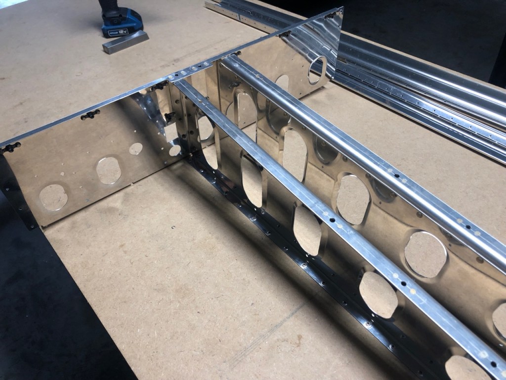
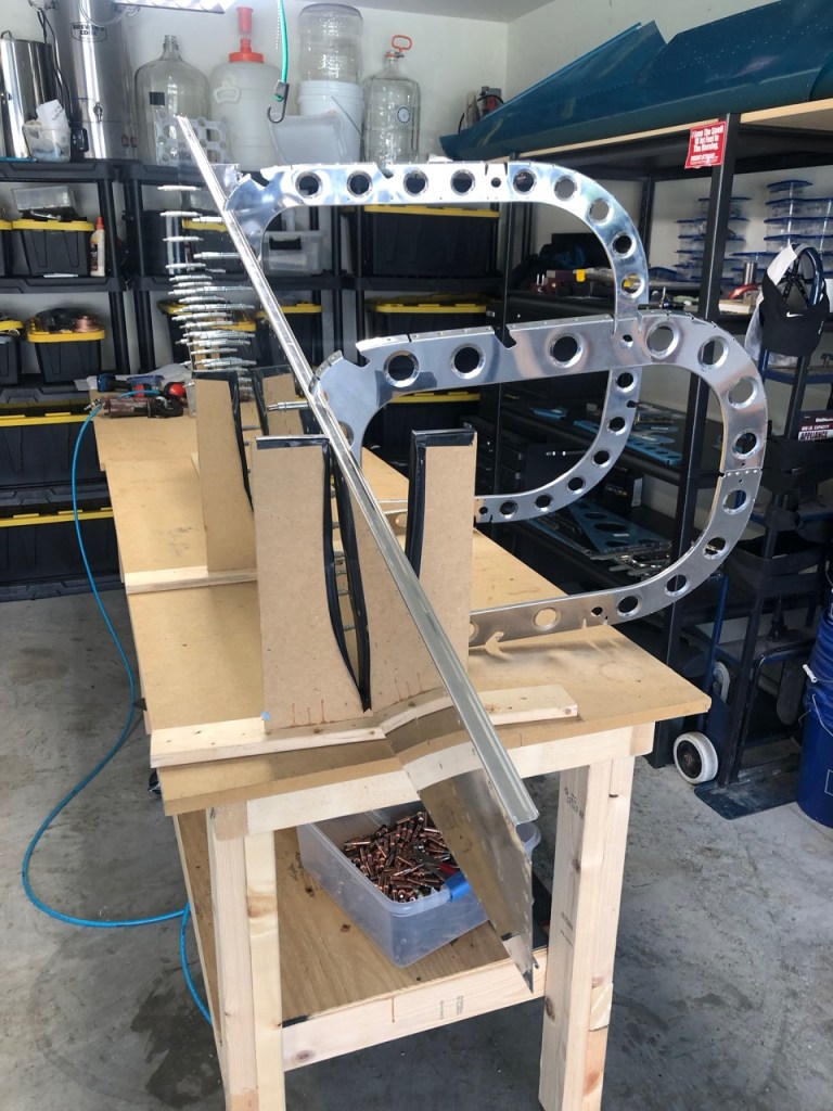
The Bellcrank ribs were attached to the forward bulkhead (relative to the Aft Fuselage) with the other end being riveted to the larger side frame bulkhead.
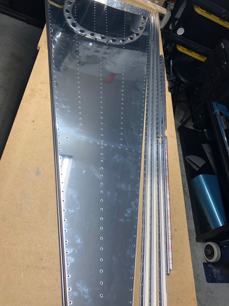
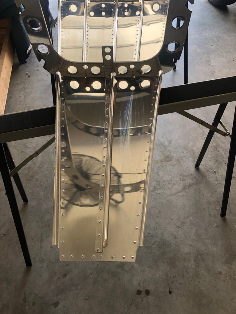
At this point it was back to one of my favorite activities: dimpling. The big sheet below is the bottom skin of the aft fuselage. It is sort of a shame to pull the blue vinyl off exposing a nice shiny scratch free surface only to immediately mar it with greasy fingerprints.

This was probably the most dimples in a single sheet so far.

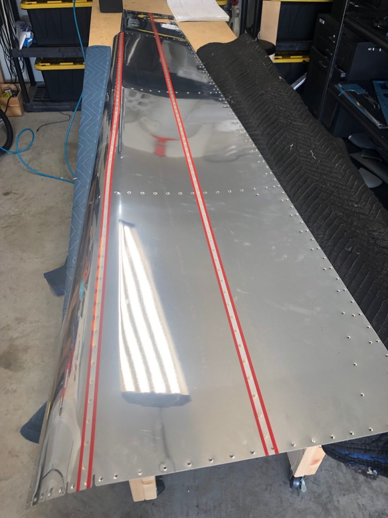
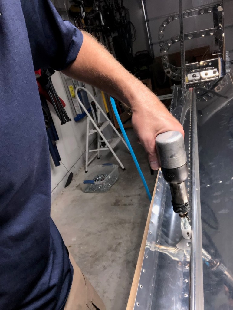
Departing from the plans a bit, or at least the conventional way of doing things, I read about online using a back rivet method on the bottom skin to stiffner attachment. As before, the rivets are inserted into each hole, rivet tape is then stretched over the line of rivets, and then you put the rivet gun on the shop head side. The flat heat of the rivet is placed against a steel plate to act as a big giant bucking bar. The results leave a very flush and smooth set of rivets on the skin.

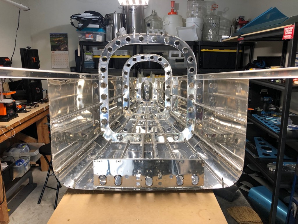
While upside down and on saw horses, the larger side frames and bell crank ribs are cleco’d to the bottom skin. This done upside-down due to gravitational forces.
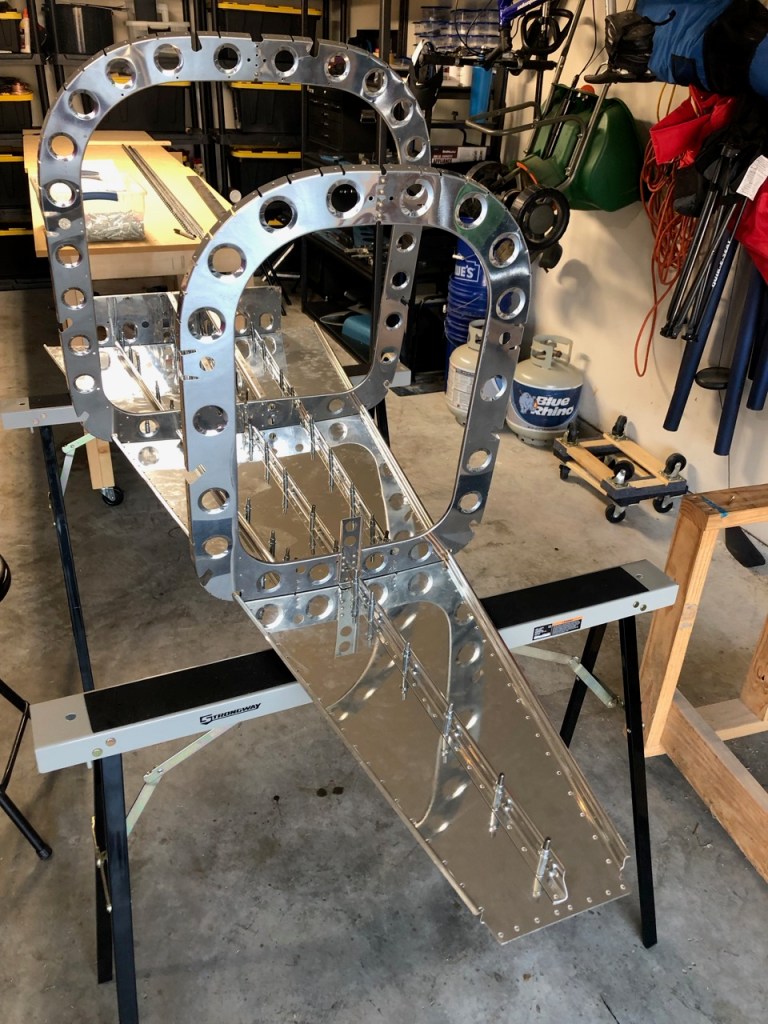
Both longerons are then countersunk to accept a dimpled skin on top of it.
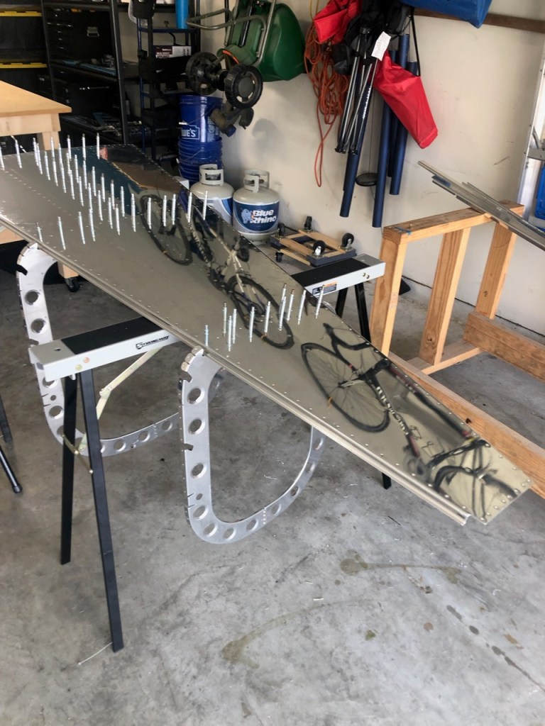
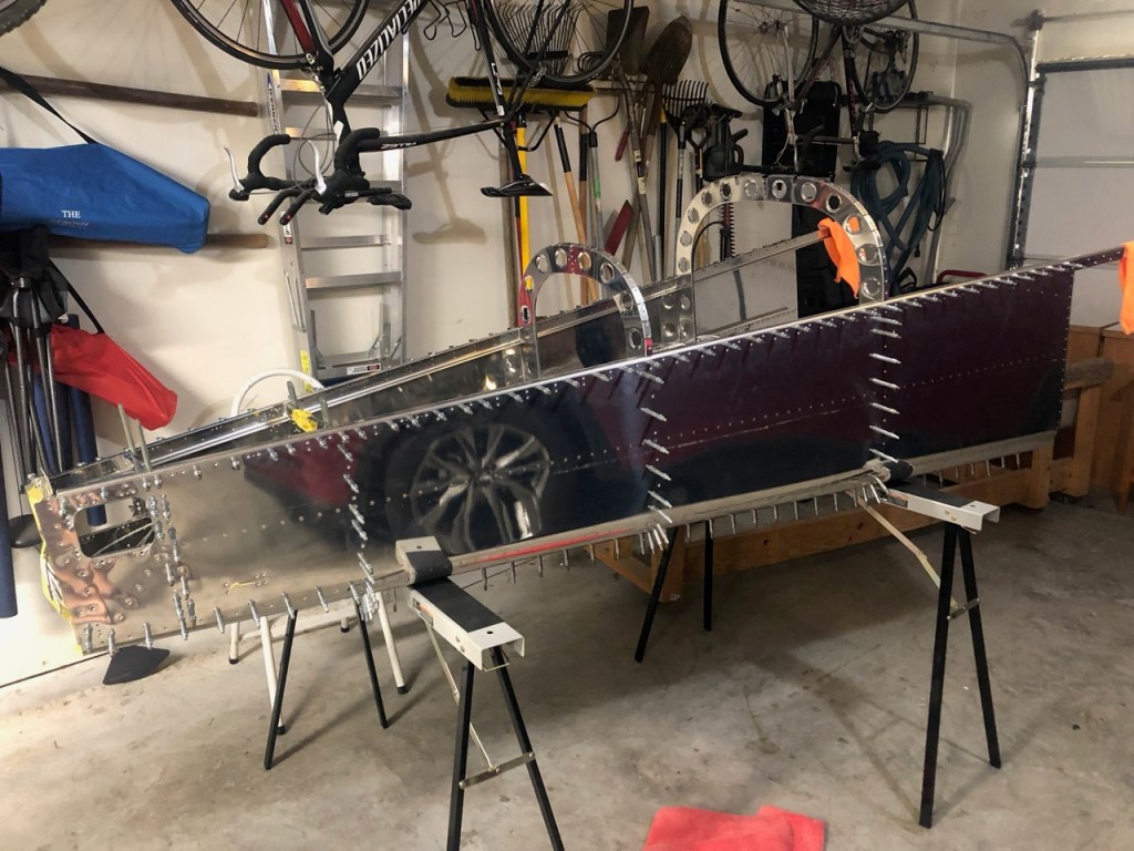
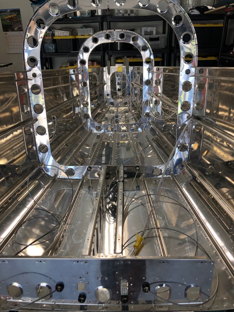
This was an exciting moment because once the side skins (dimpled previously) are attached, there was something resembling an airplane in my garage.
The lack of cleco’s disguise the fact that an awful lot of rivets will be installed later.
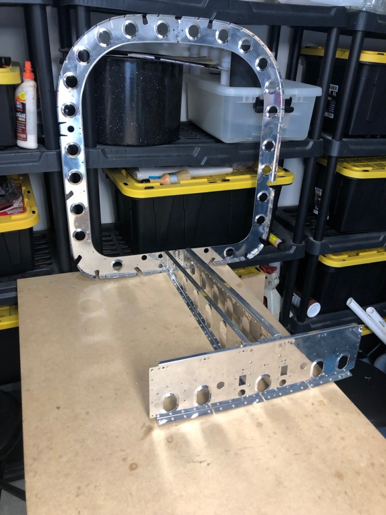
The bulkhead of the very back of the airplane was attached to a short section of bottom skin.
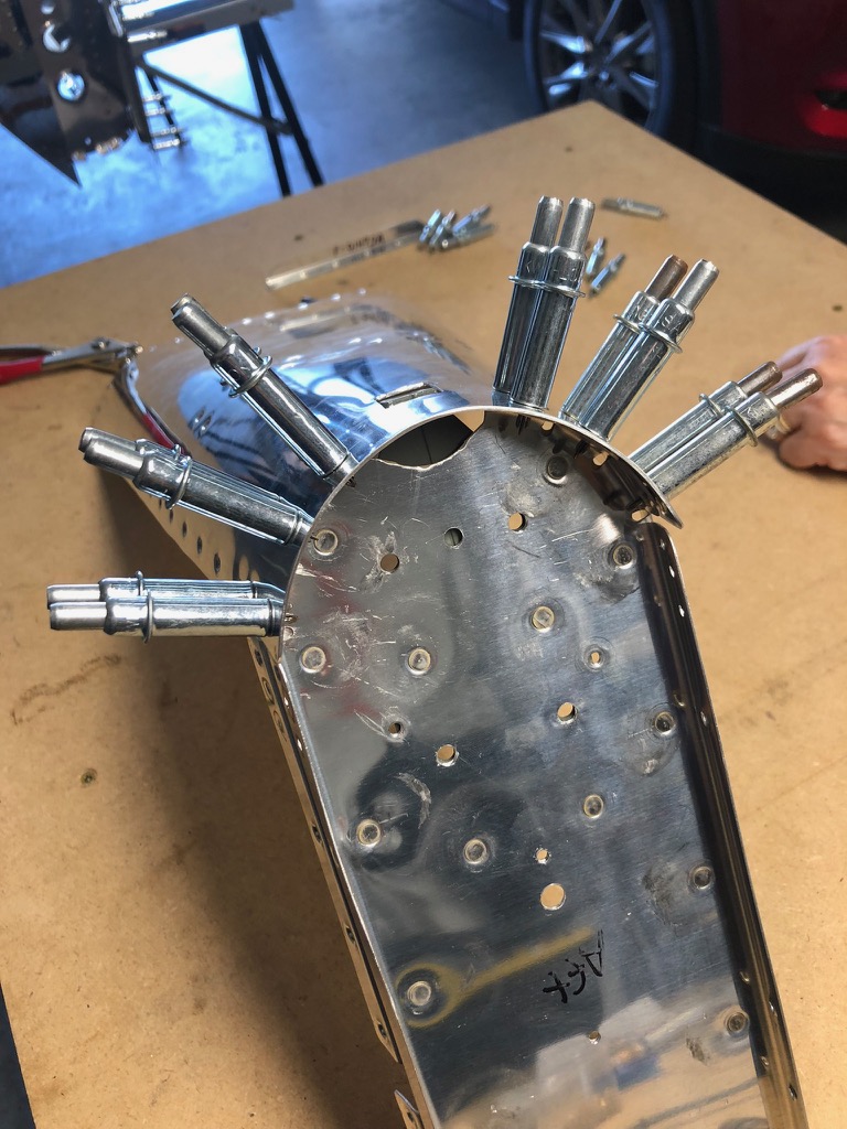
And then it is was attached to the rest of the assembly.
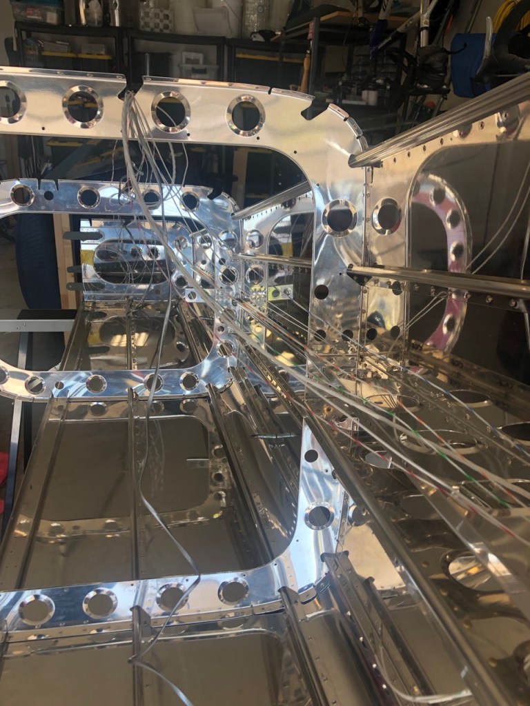
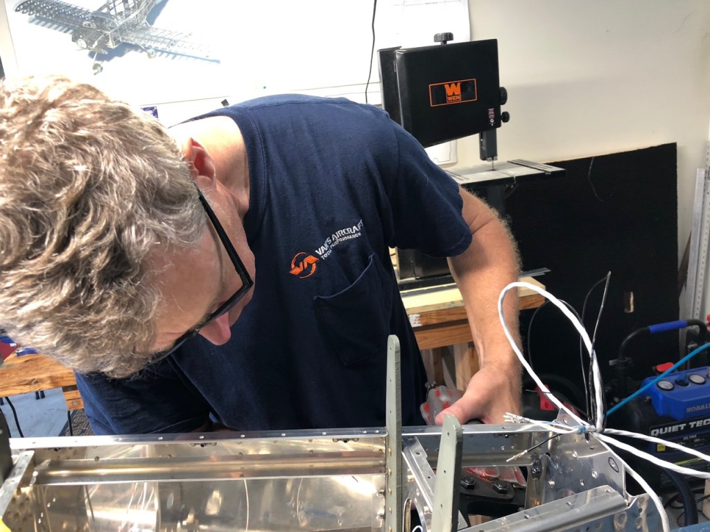
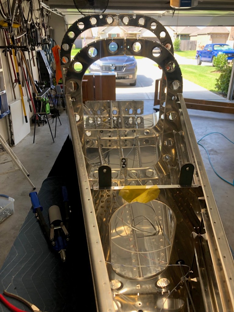
It was at this point where the wiring for things in the rear of the airplane was installed. This was done now because the wiring needs to be in the channels between the bulkheads and the side skins before riveting. For now, it was a spider web of wires and such but this is cleaned up later.
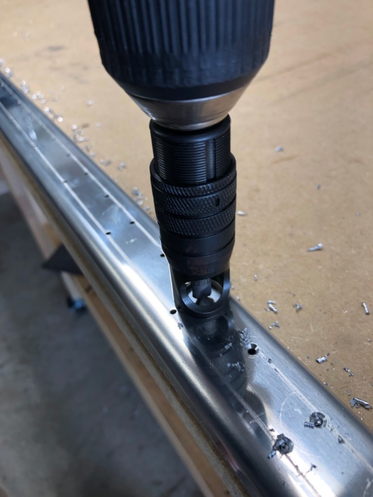
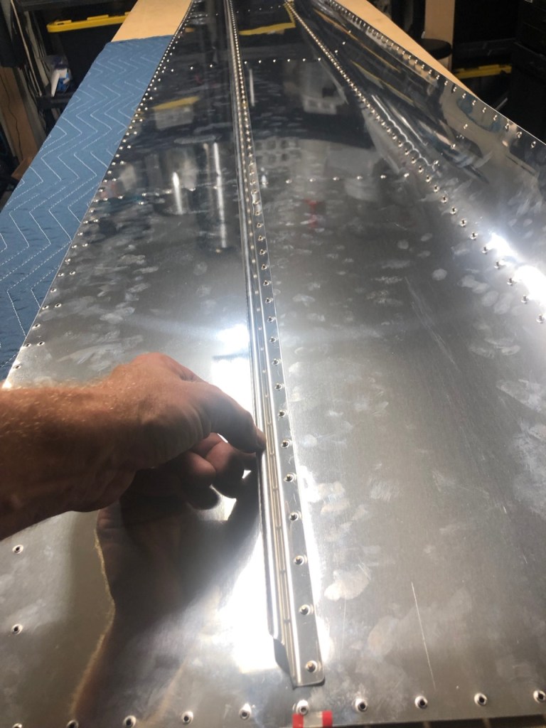
Using the same back riveting method on the bottom skin, I back riveted the two stiffeners on each side skin.
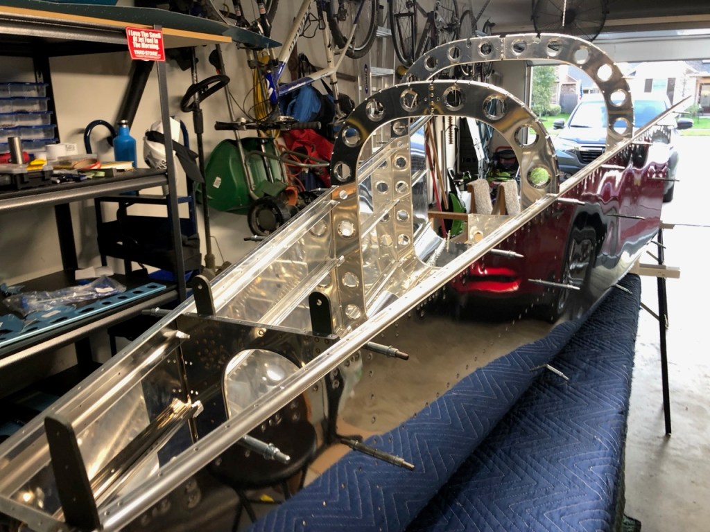
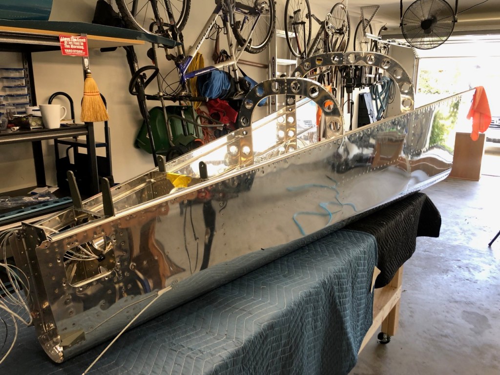
Cleco’ing the side skins to the other parts for the final time, I started to see the Aft Fuselage taking shape….or a canoe.

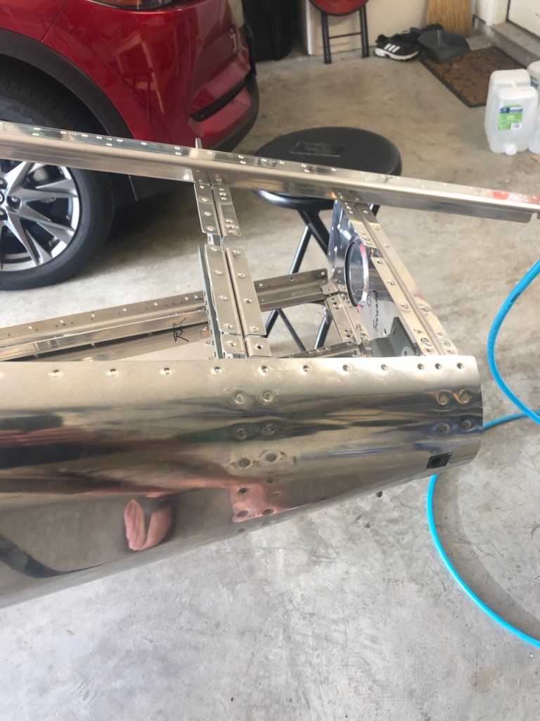
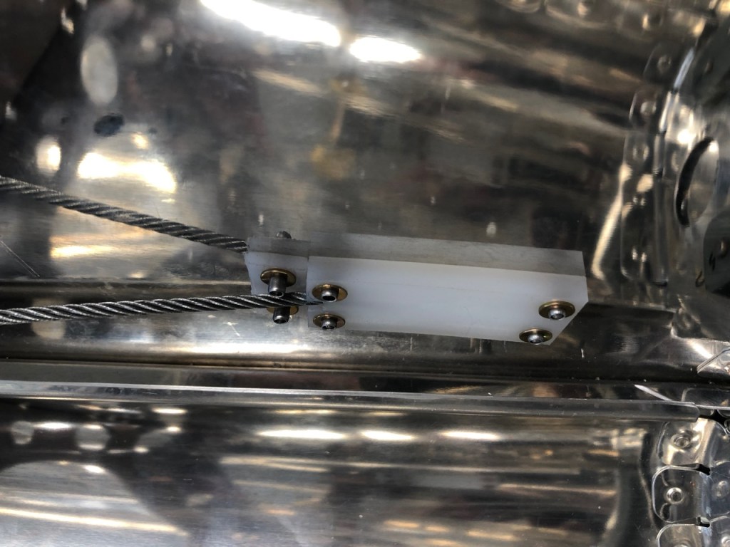
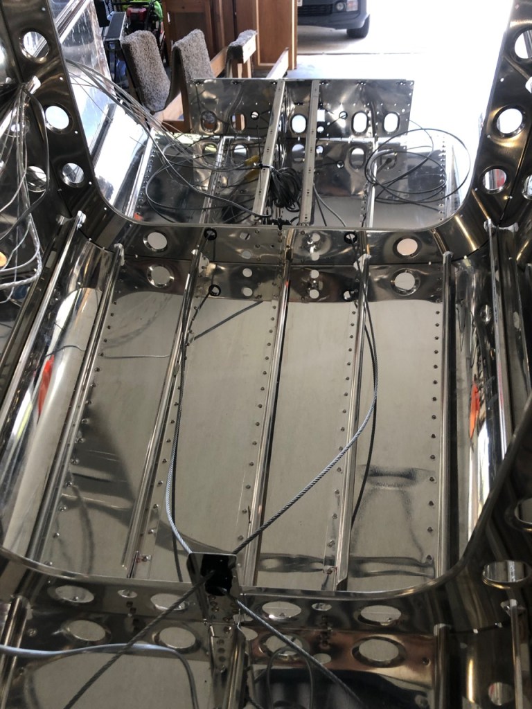
At this point I installed the rudder control cables. The picture below shows the exit point from the side skins. Teflon spacers and blocks are used to prevent the cable from cutting into the aluminum skin.
With the side skins riveted and everything upright, the tangle of wires is still to be organized. These wires consist of the power wires for the taillight strobe, the power for the Elevator trim tab, two antennae wires, and communication and power for the ELT.

I’m just blown away. I’d love to sit in your garage/shop and observe the process. I respect if from afar and i know i would be totally wide eyed if i saw it first hand. Sweet!
Randy, if you come to see you will surely he recruited to help out.