
Several months ago I talked about the process of designing and planning the avionics panel. I also started the wiring of the panel harness which was then put aside until I could buy all the panel components. Well, today I can say all that work is complete. The all Garmin panel is up and running, and everything seems to be working properly.
I didn’t really track the hours that this took to complete so I am estimating 200 hours from the time I started researching, planning the schematic, copying other’s work :), doing the wiring, designing the aluminum structure for the panel, and installing the components (LRU’s).
The panel consists of the following, all made by Garmin:
- 2 G3X 10.6″ screens, Primary Flight Display (PFD) and Multi Function Display (MFD)
- GNX 375 IFR Navigator GPS with ADSB In and Out Transponder
- GAD 29 – ARINC (used to let the Navigator talk to the g3X screens
- GEA 24 Engine Analyzer – all the engine sensors go through this box
- GAD 27 – Electronic Adapter Unit – runs the flaps, trim, and lights
- Vertical Power VPX Pro electronic circuit breaker
- GDL 51R – XM radio receiver
- GD40 – CO detector (not made by Garmin)
- TCW Back Up battery
- 2 Comm radios
- GMA 245 Audio Panel
- GMC 507 Autopilot controller
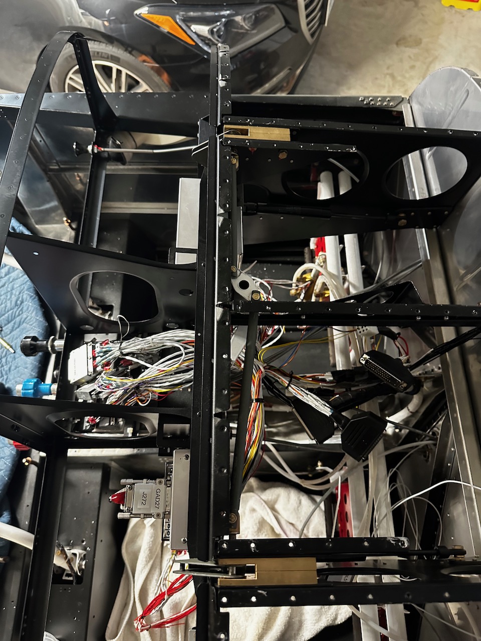
I will start by showing the panel harness I put together last May which sat idle in a box waiting for its big moment. The pictures below are a very brief overview of what went on over the last 3 months.

The harness was placed inside the avionics area forward of the cockpit.
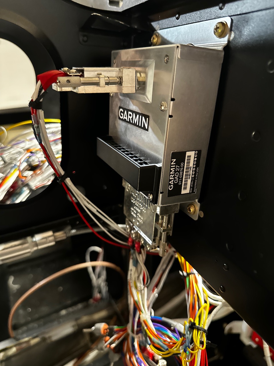
About a dozen Garmin boxes were installed into various places in the panel. The hope was that the harness connector would attach to the boxes in the right place with the right amount of service loop. Below is the GAD 27 which controls the flaps, lighting, and trim motors.
I decided to go with a Vertical Power VPX electronics circuit breaker. This eliminates dozens of physical circuit breakers that would need to be placed somewhere. The ECB’s are controlled through the G3X screens on the panel.

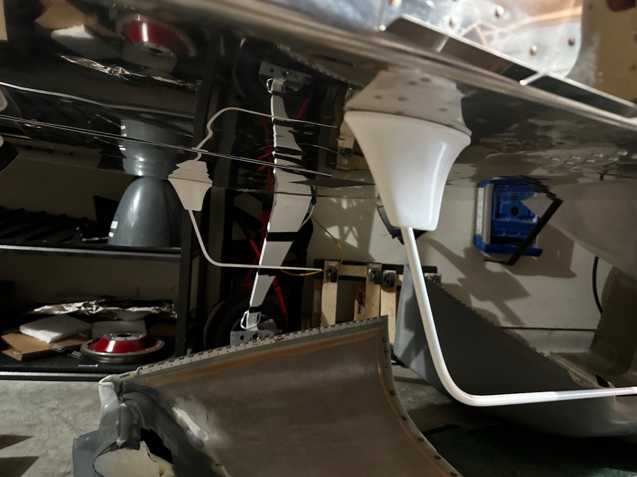
The two comm radio antennas are installed on the belly below the cockpit.
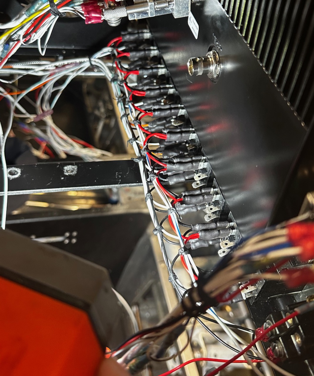
I decided to go with lighted Honeywell rocker switches to control various components.
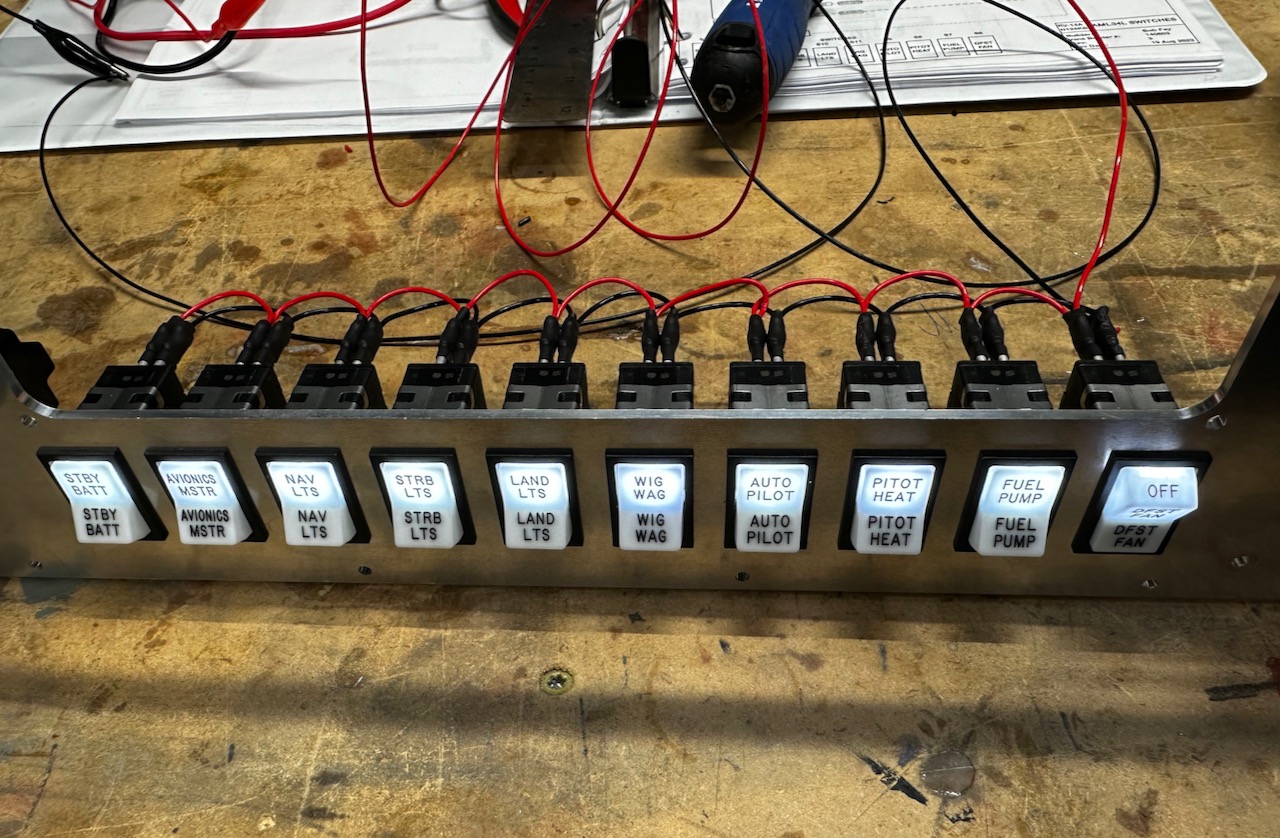
Below you can see the wiring to the switches on the backside of the panel.
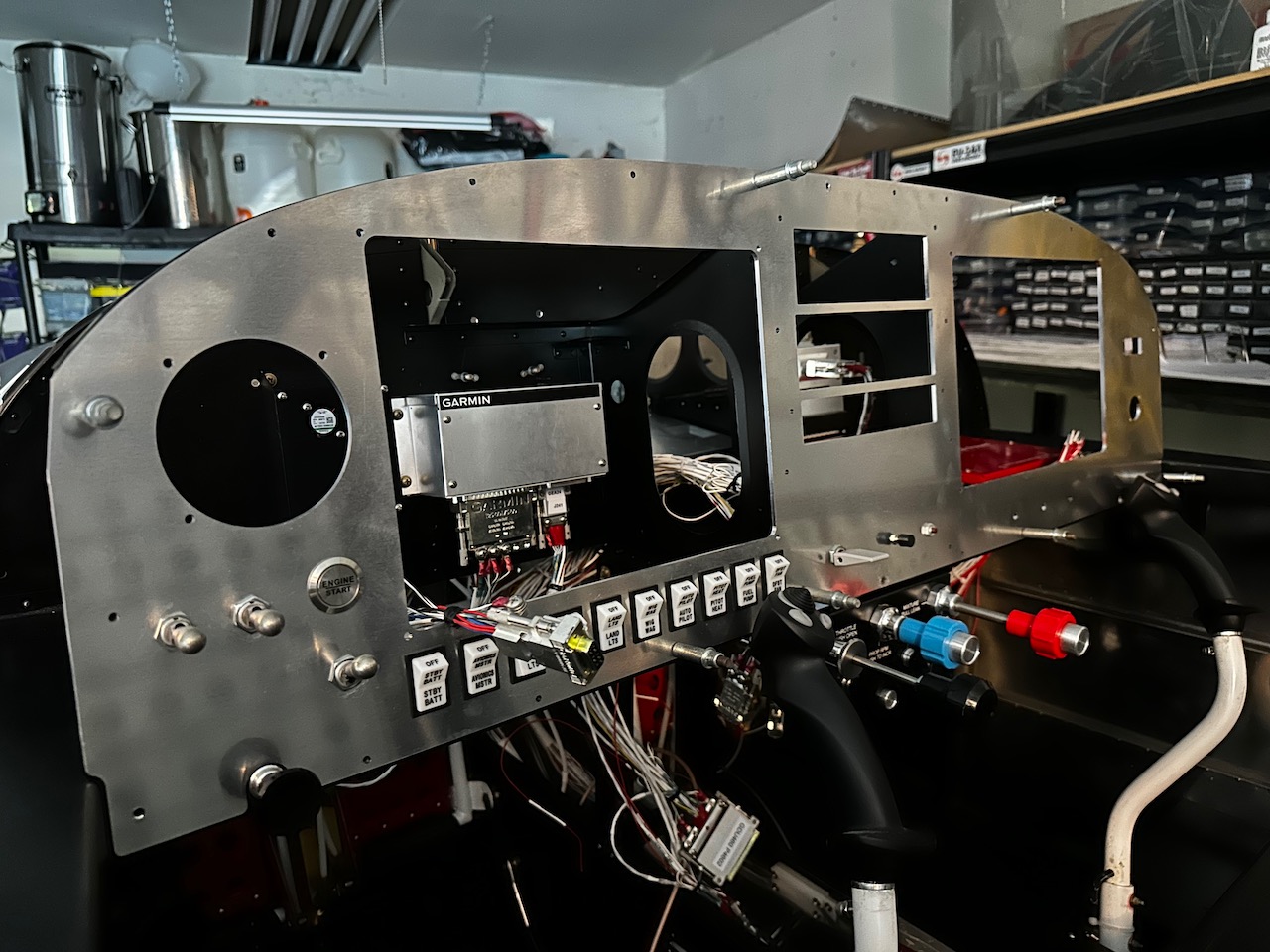
I initially went with a unpainted prototype panel to ensure everything fits before ordering the final, powder coated and labeled panel. This cost about 1/2 of the final panel but it was worth it. I had to make some adjustments to things after receiving this.
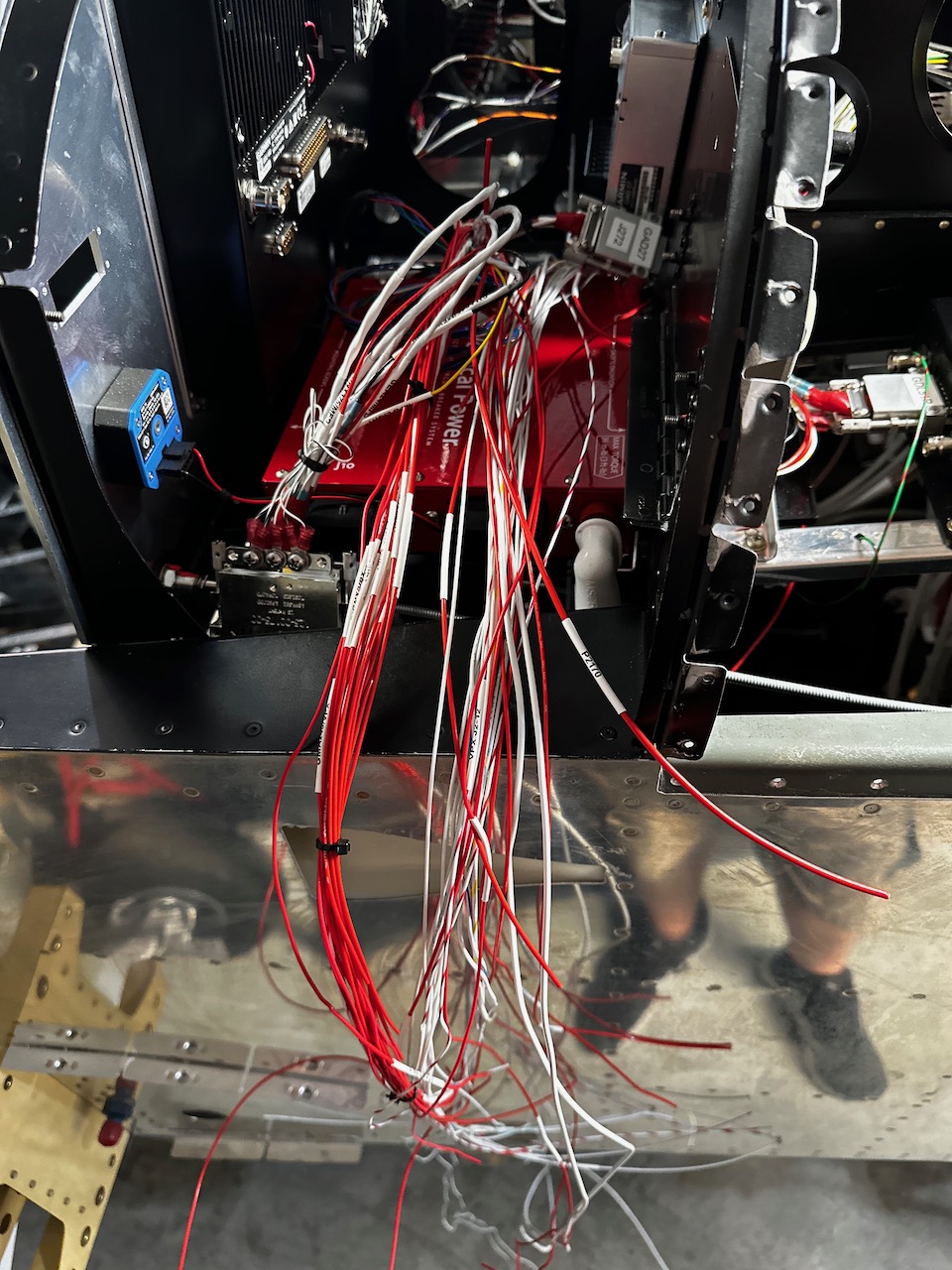
This shows all the power wires brought over from the various components to the Vertical Power VPX.
And here are the wires terminated with connectors and put into somewhat of a more organized manner.
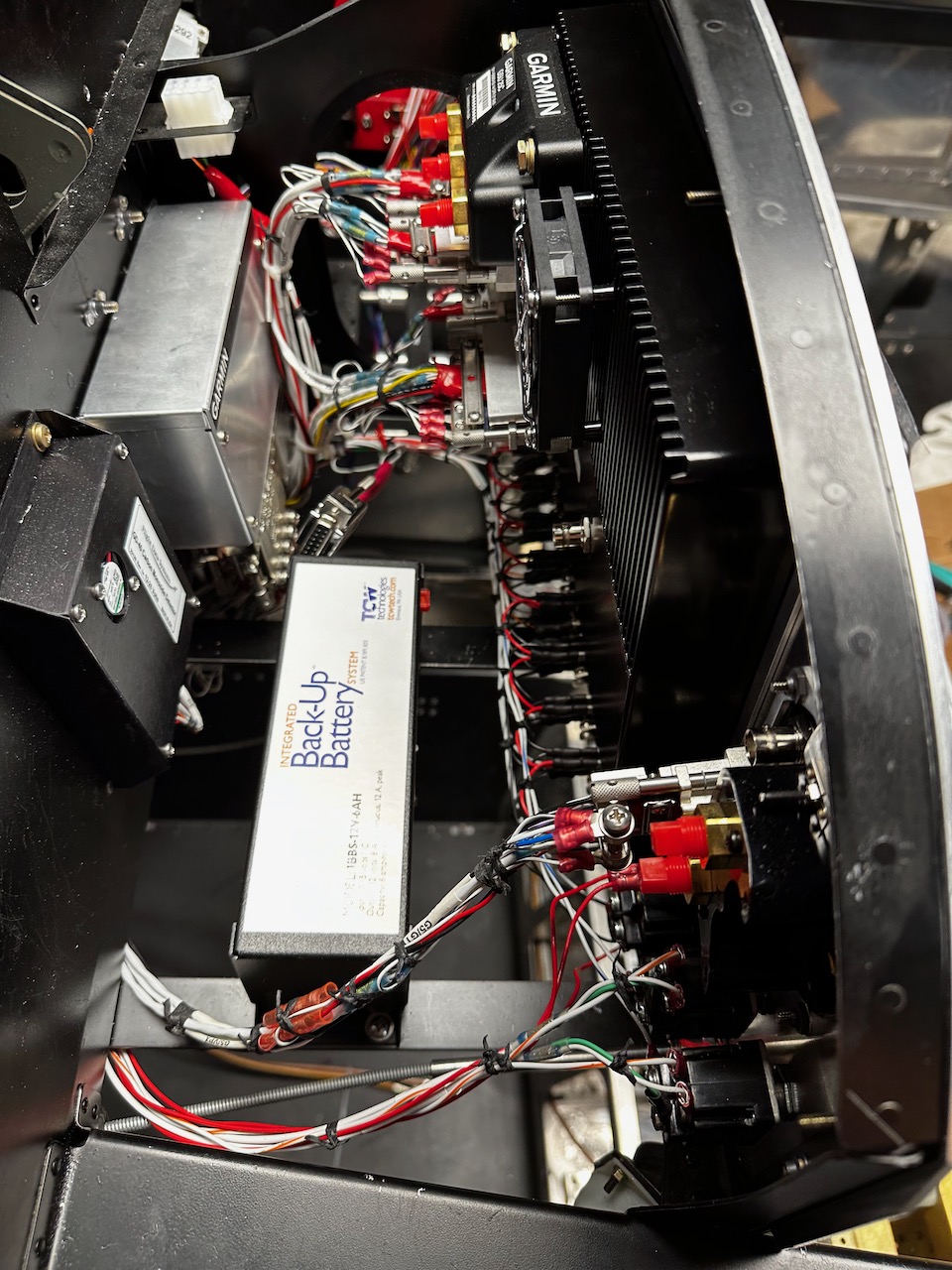
Below is behind the pilot side screen. The TCW Back-Up battery is there to provide about an hour’s with of power to the panel if the alternator fails.
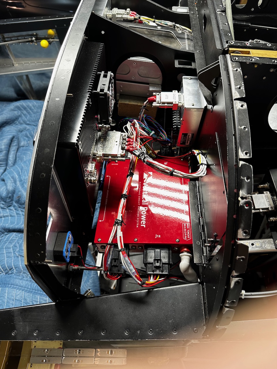
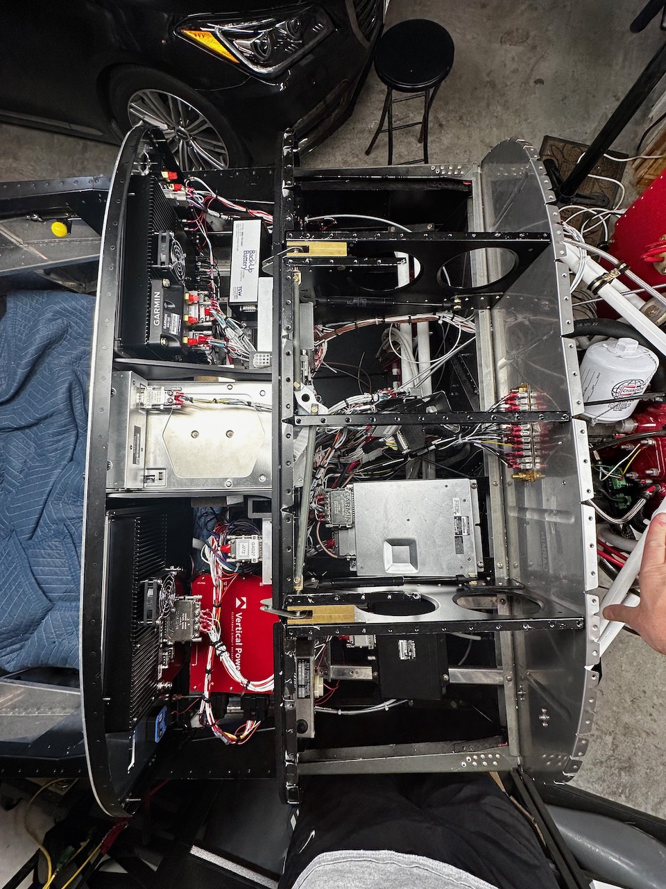
I am skipping way ahead but this is a mostly final top down view of all the stuff behind the panel.
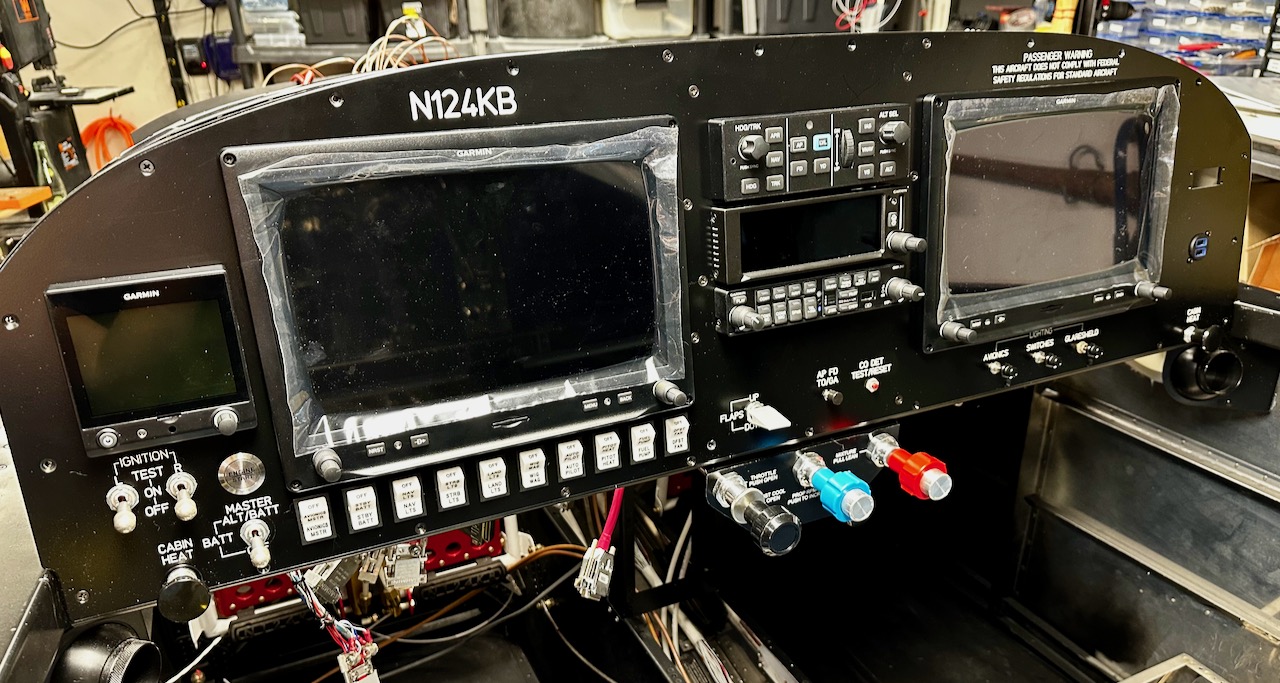
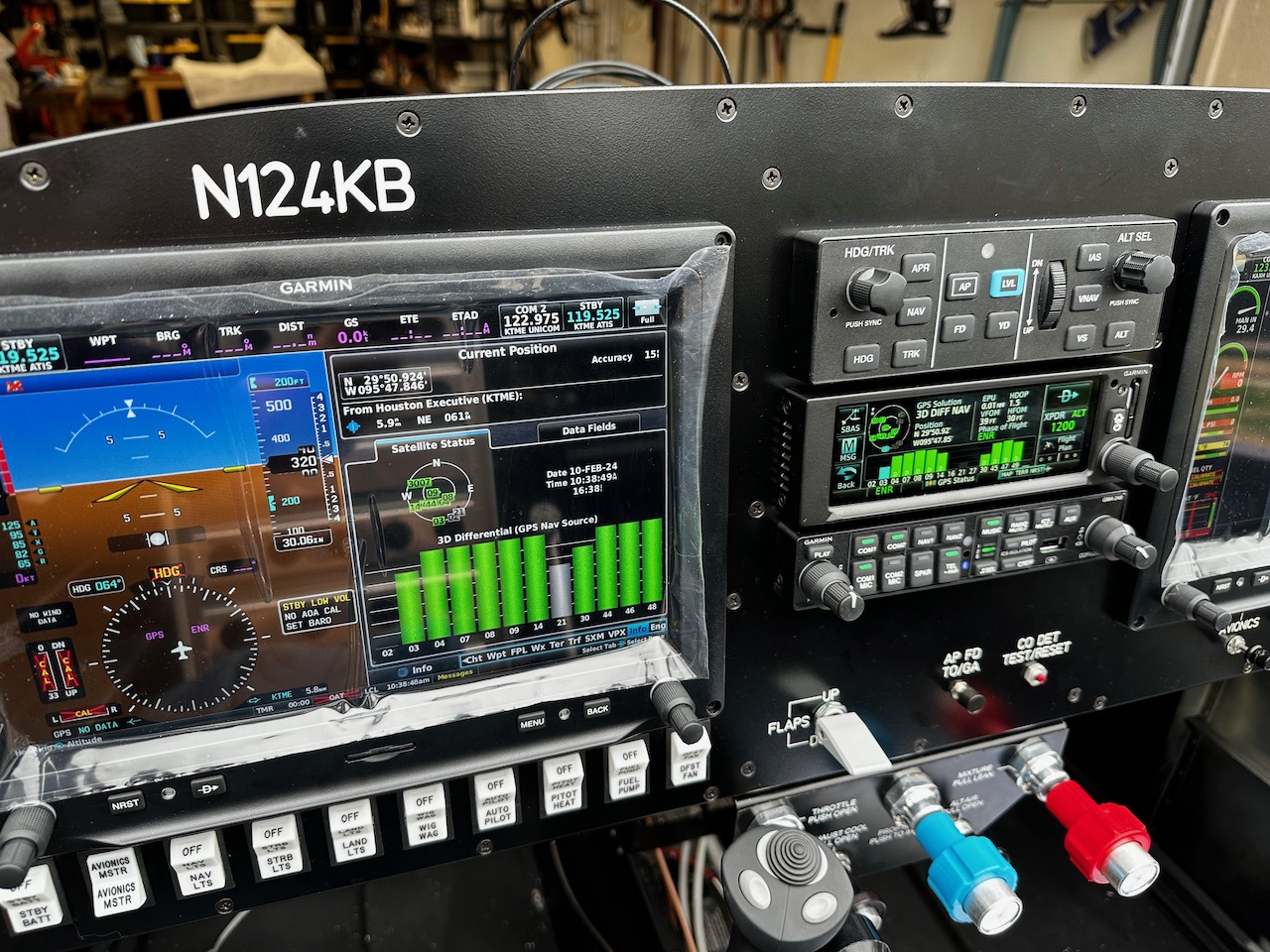
And now, here is the final panel all put together and waiting for the initial power up. I went through the entire harness twice checking for proper wire attachments, proper polarity, and short circuits.
The big fingers crossed moment came when the stuff was finally turned on. I am happy to report that everything is working as it should be and everything talks to each other.
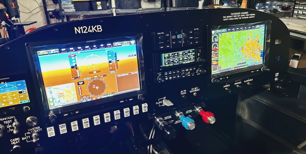
The airplane was pulled out of the garage to let the GPS antenna’s find satellites. The green bars meant something good was happening.

It’s so cool to see this coming together. You have honed so many new skills and I marvel at your courage. Way to go!
Nice job tidying up those harnesses. I wonder how many actuations those rocker switches are rated for.
I love the look of the powered up panel. So, so cool!