
It has been several months but that doesn’t mean I have been idle. For the last 14-15 months, in parallel with the other steps, I have been planning the schematic for the panel. In fact, I estimate that I have put well over 100 hours into the schematic alone. Using a combination of internet resources, other builder’s plans, Garmin manuals, I have come up with a “Wirebook” consisting of about 80 pages of wiring diagrams. This took a really long time to complete (still not sure I know what I am doing) but I think it is mostly there, and now that I have done a lot of the harness building and wiring, the work has really paid off. At least now, I have a very good understanding of what is going on with the wiring under the hood.
The panel will be a complete Garmin panel with 2 10.6″ displays, G5 backup attitude indicator, autopilot, audio panel, 2 Com radios, a GNX375 IFR Navigator/Transponder, and all the associated boxes inside including an ARINC, ADHARS, engine analyzer, Pitch and roll servos, magnetometer, and a bunch of wires.
Instead of traditional circuit breakers, I will be using a Vertical Power VPX Pro which acts as electronic circuit breakers. This also ties in directly with the Garmin g3X system so that I can closely monitor all the components of the system.
The wire book consists of a lot of diagrams like this:
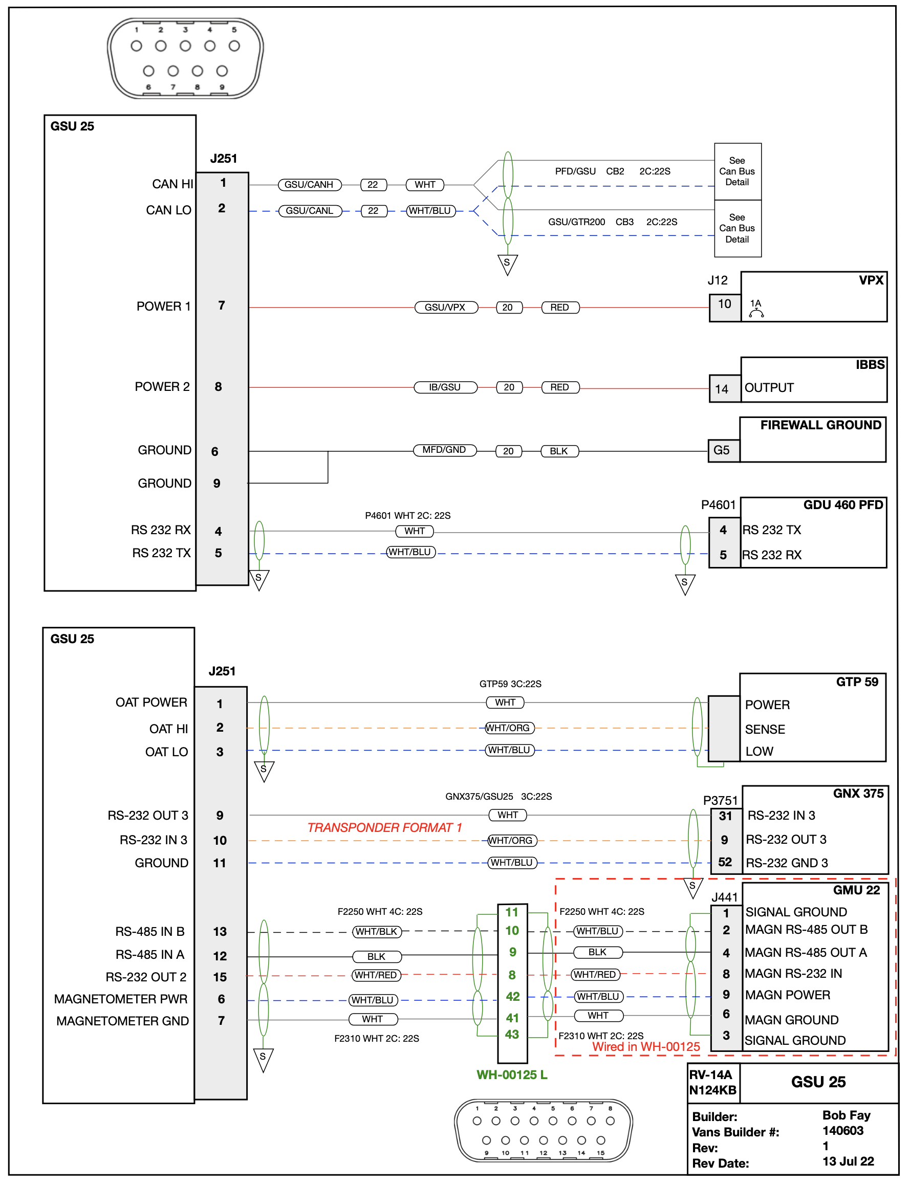
This plus many other pages like it are what I am using to build the panel. Oh, yes, this can all be done by someone outside, costing many thousands and thousands of dollars, but I decided to do myself in order to, yes, save many thousands and thousands of dollars, but also to have a better understanding of how the airplane works. Besides, this is a lot of fun.
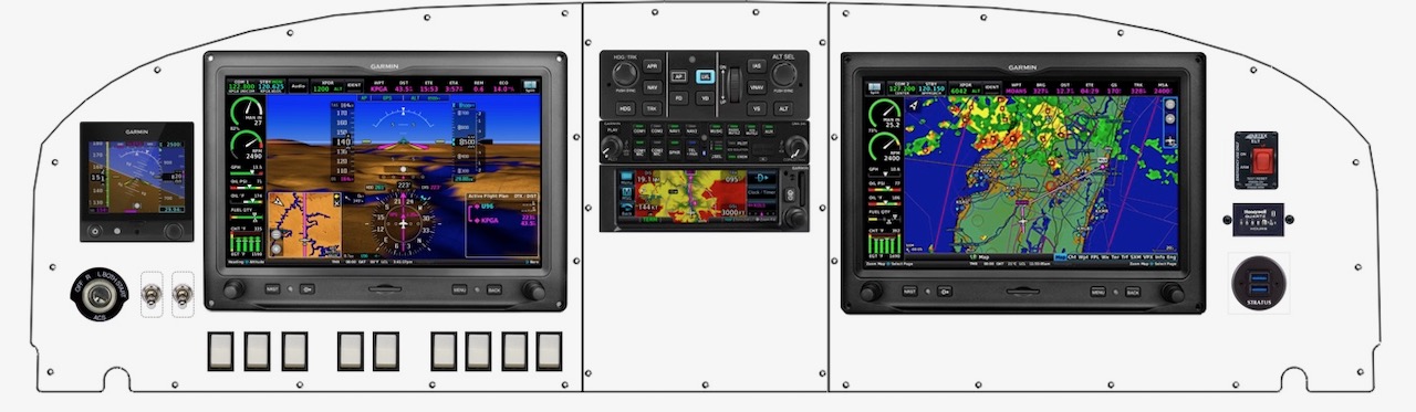
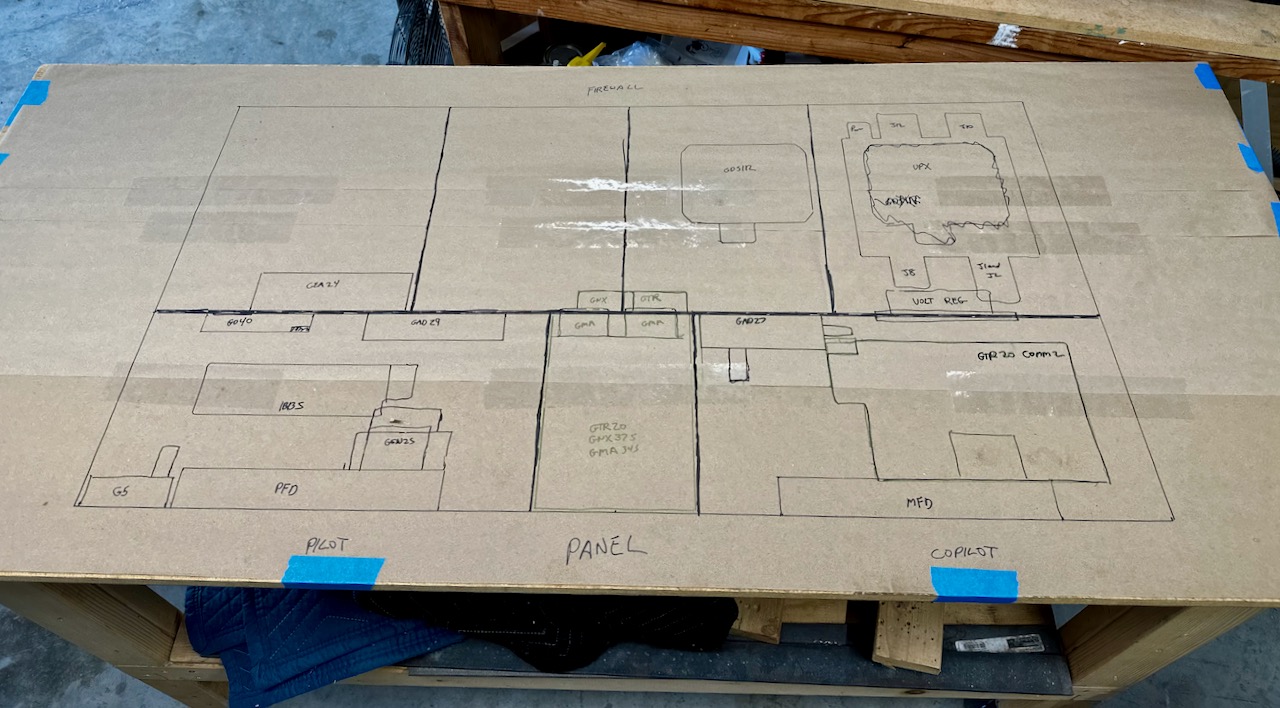
While not exact, the panel will be similar to this:
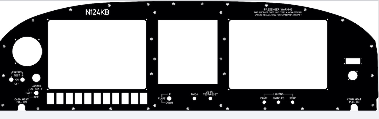
In fact, I am designing the metal part of the panel itself, and will have it made by Front Panel Express (https://www.frontpanelexpress.com). Right now, the panel looks like:
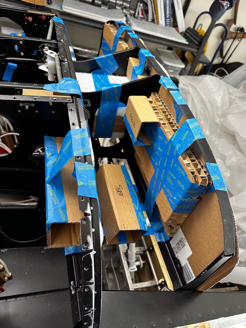
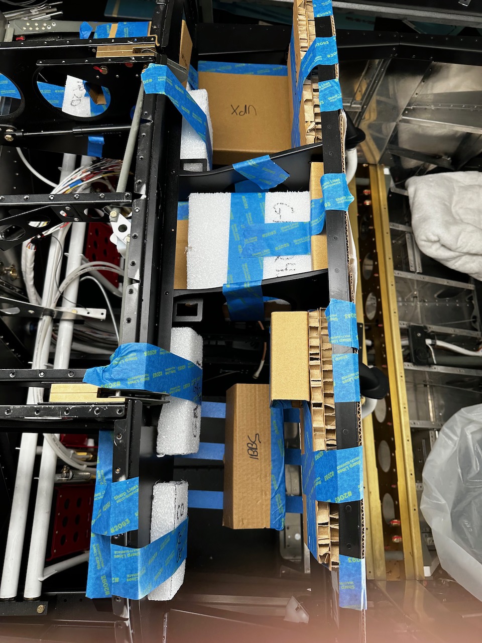
In the past two months, I started to work on the wiring. First, I mocked up the panel and the components, printed it out, mounted on cardboard, and placed it inside the airplane.
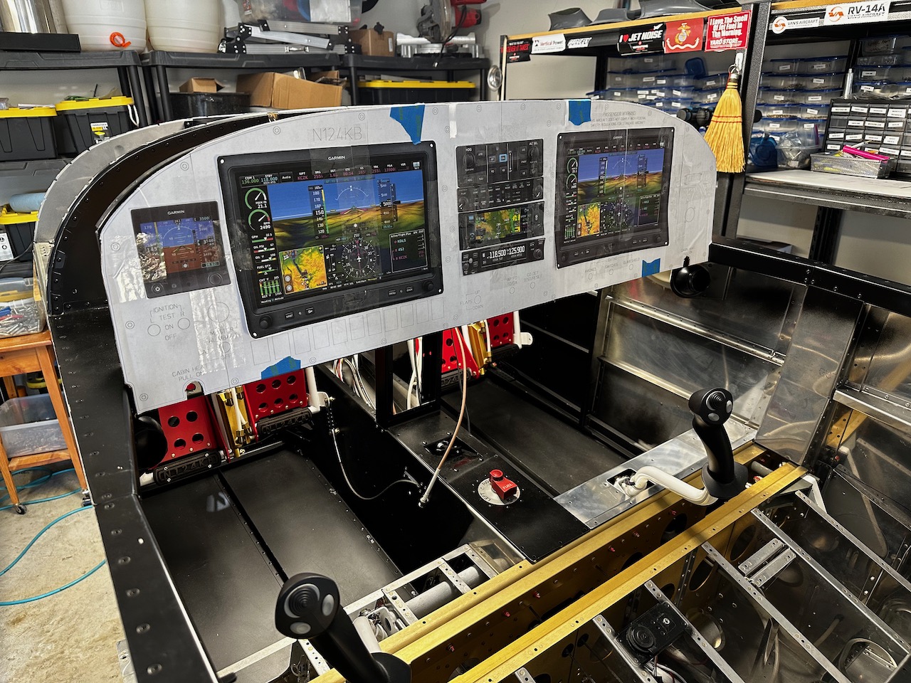
I was given some foam block cut-outs by a builder friend as well as made some of the missing ones from cardboard. I found a home for everything with the purpose being a means to determine wire lengths for the various harnesses.
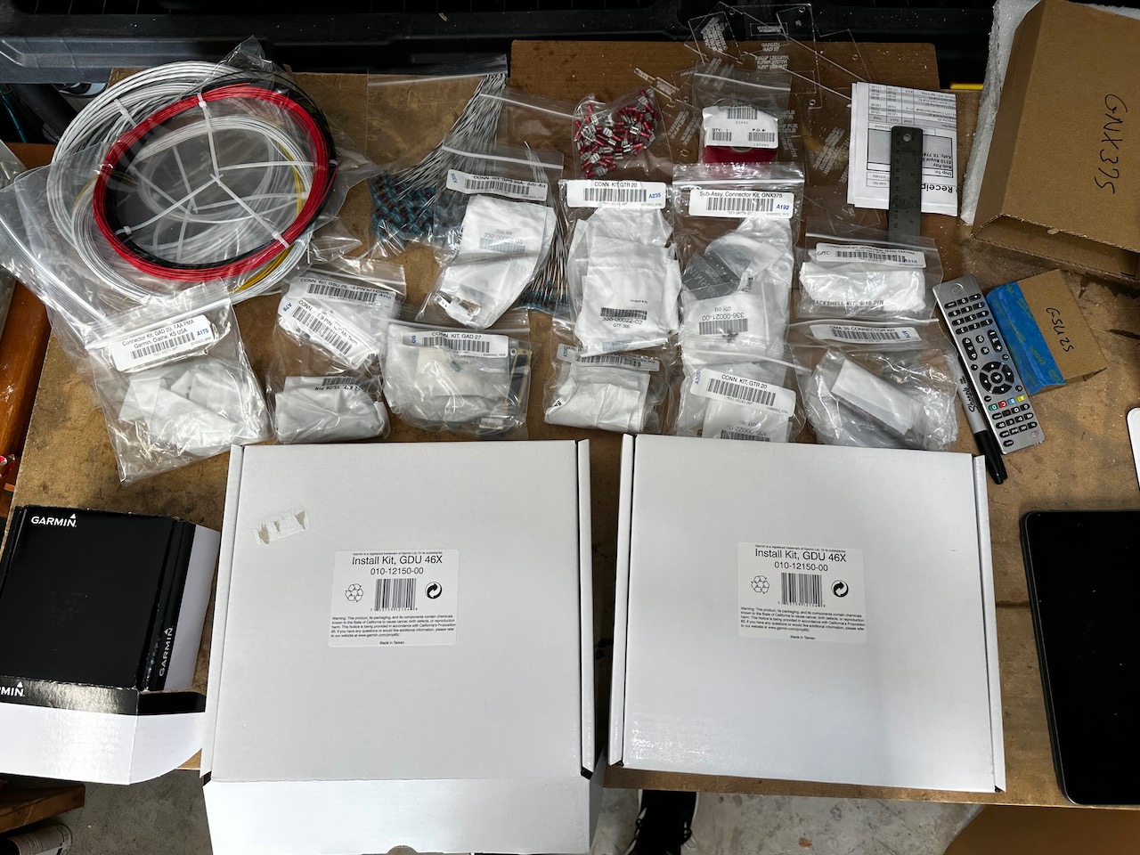
To help ease or spread out the pain of buying everything at once, Garmin has “connector kits” for all of the components. I bought most from Steinair (https://www.steinair.com) where pretty much everything will be purchased from.
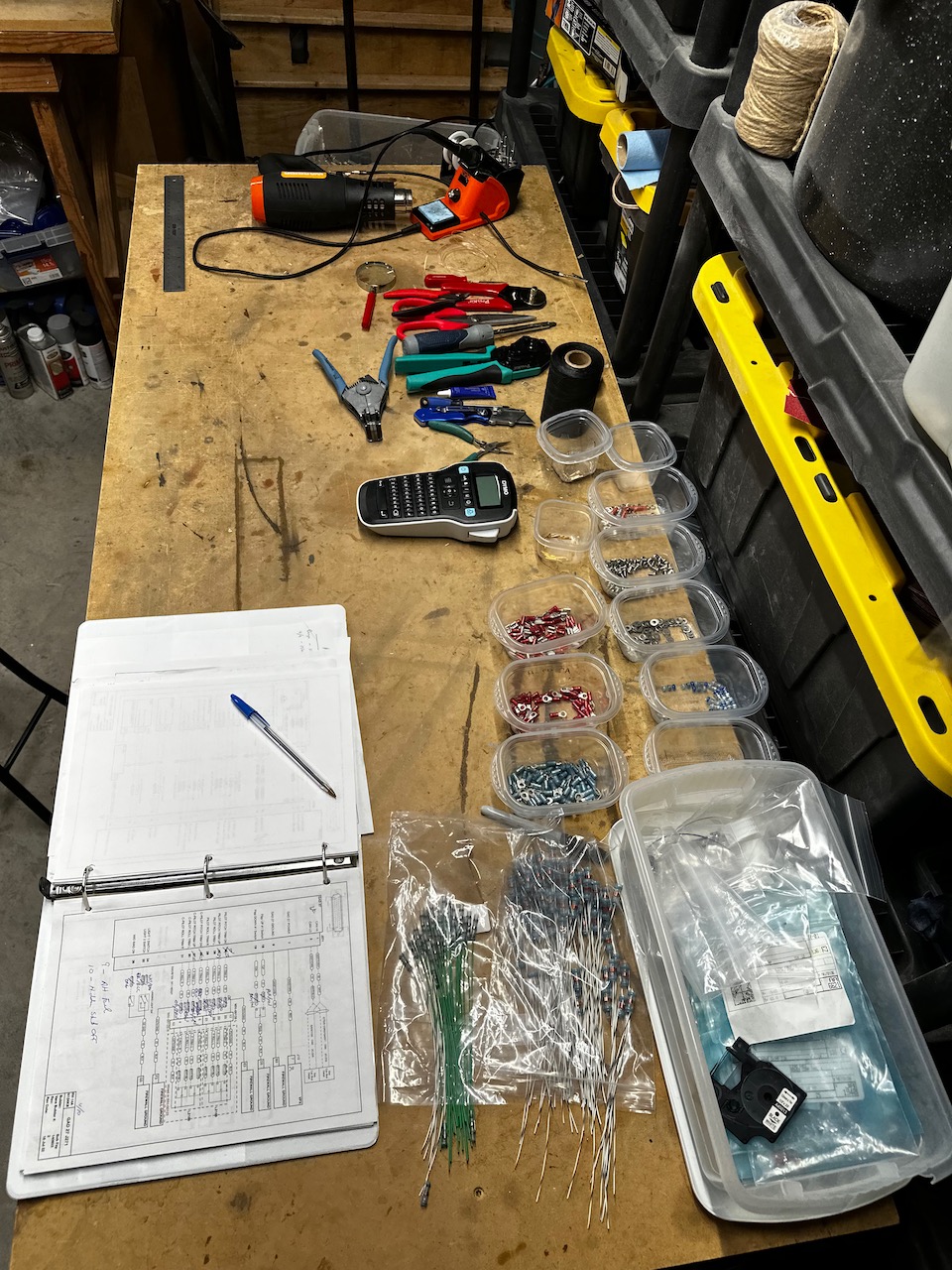
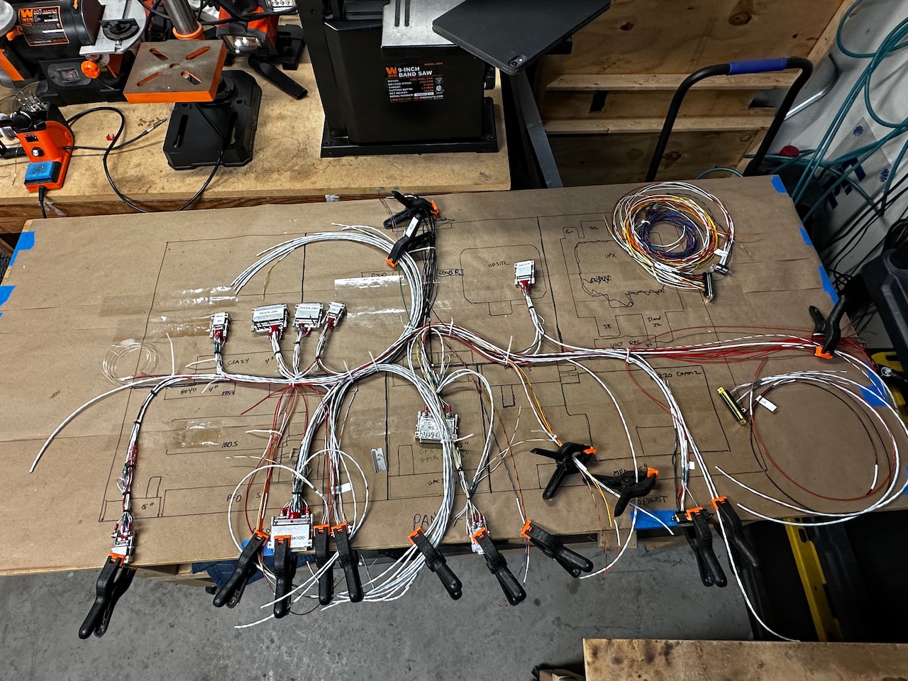
Also, the wiring table was prepared with tools such as strippers, cutters, crimpers, hardware, solder sleeves (the greatest invention to mankind), soldering iron, heat gun, and tissues for when I start crying after making a mistake.
All of the connector harness terminate with a Dsub connector with various pin or socket numbers.
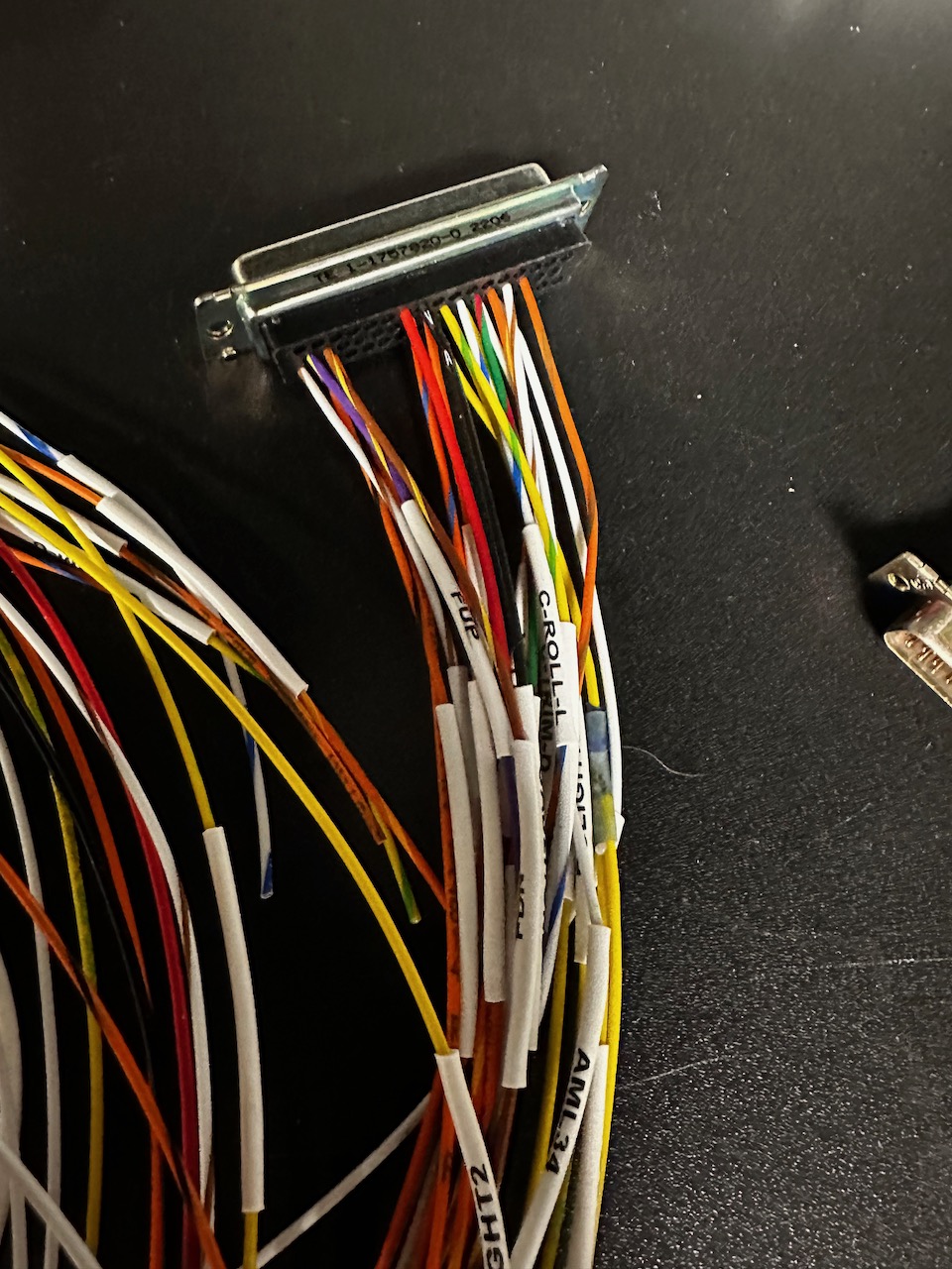
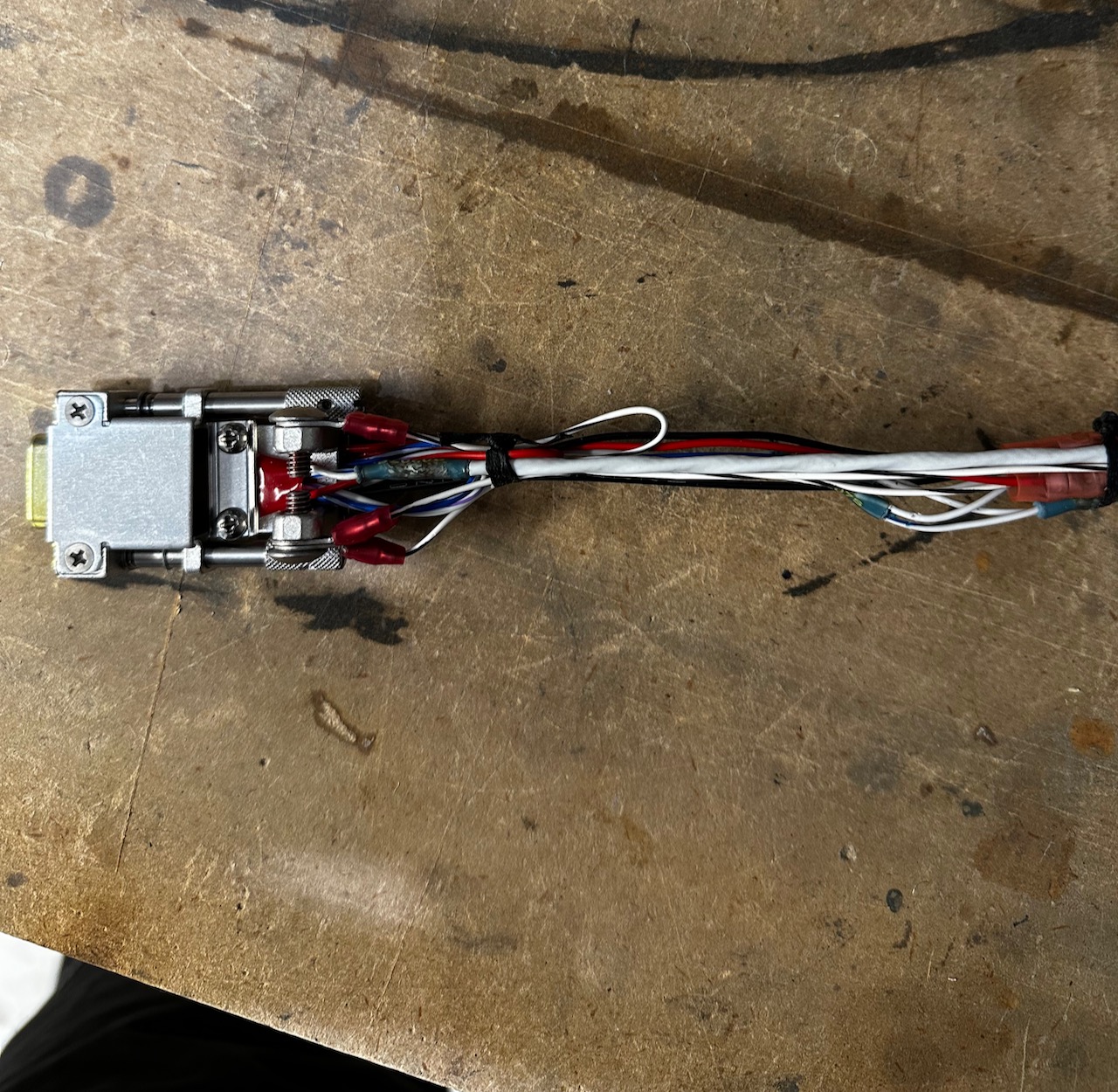
Not to bore you with the details of making these, eventually, I ended up with 22 harnesses
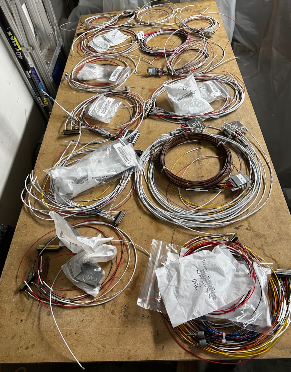
Along the way, I put a few inside the panel to check my work, but most of the wire lengths were determined by using a piece of fishing line.
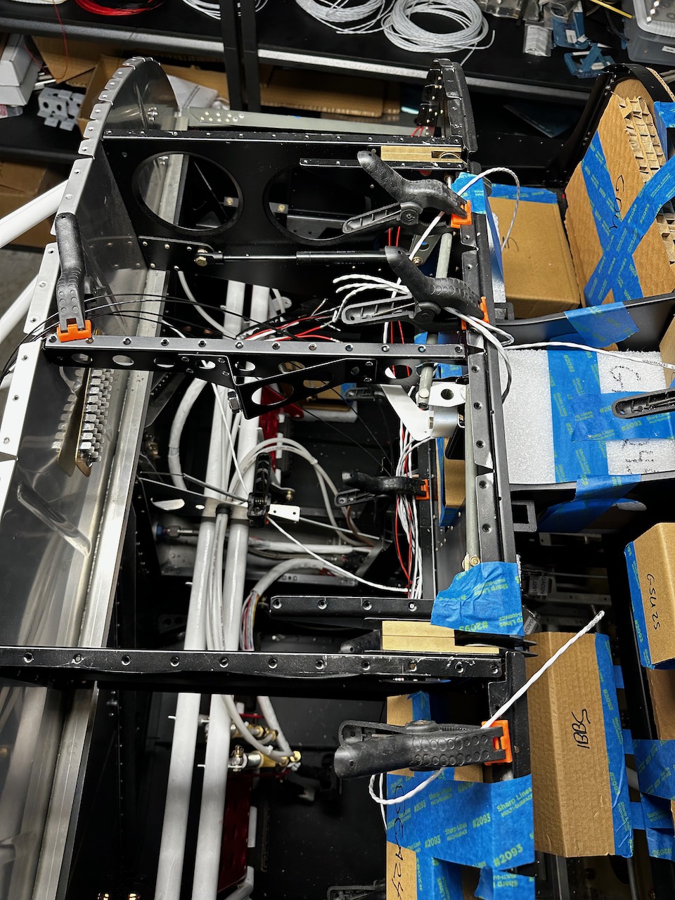
So, I bring us up to early May 2023, and I am in the process of trying to connect everything together. I think it would be virtually impossible, not to mention back breaking, to do it all inside the panel. So, I have laid out a top down view of all the components, and I am using this as a template to wire the harnesses together. I have to get the lengths correct on the first try otherwise I will be reaching for that box of tissues.
I expect this work to continue over the next few weekends. I will check in later with an update.

This is so incredible. Mike M must be looking over his shoulder. I think this is so great and I feel a great deal of pride watching you see this through and very technical as well. Way to go!