It’s been a while because….this took a while. A big hurdle is now complete: the fuel tanks!
I left off with riveting the skins to the tank ribs. Well, this just simply took a long time. Once complete, I went over it 6-7 times to make sure every possible place of leakage was covered with proseal. I ended up using about 40% more proseal than planned.
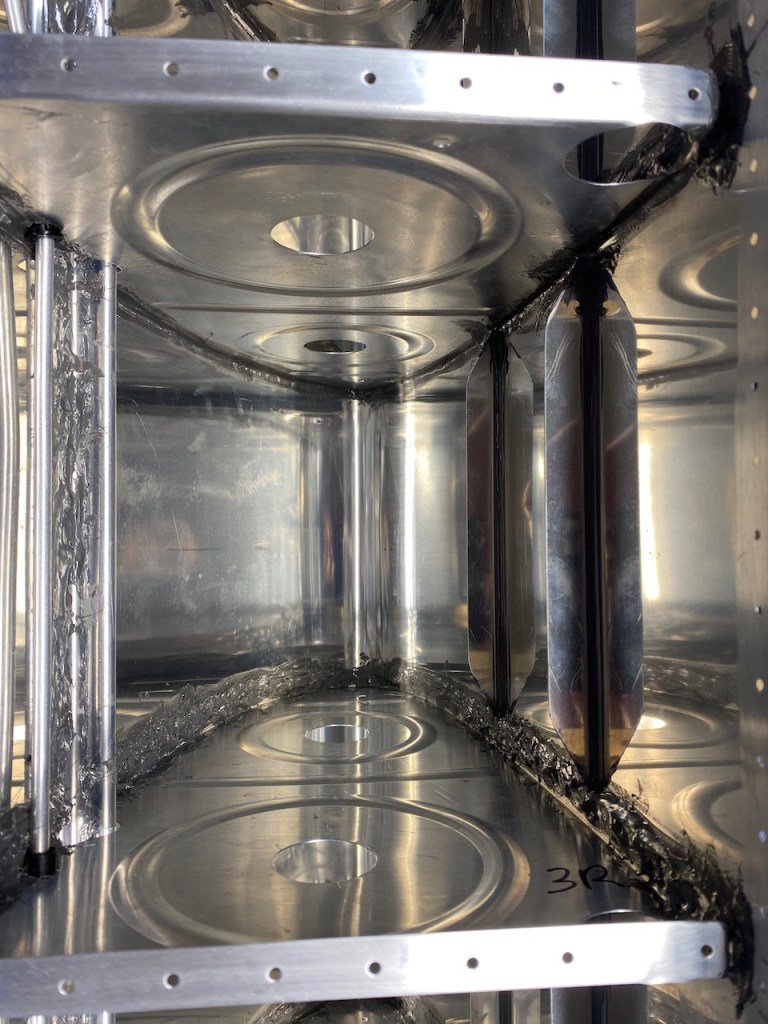
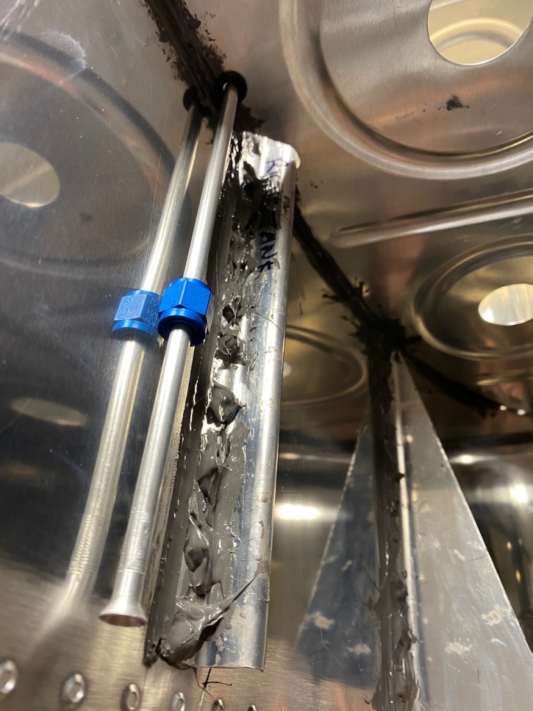
Inside the tank is as per below. I added proseal to all the rib to skin intersections. You can see all the black gooey stuff lining the corners. Perhaps I reduced the tank capacity by 0.1 gallon but it was worth it.
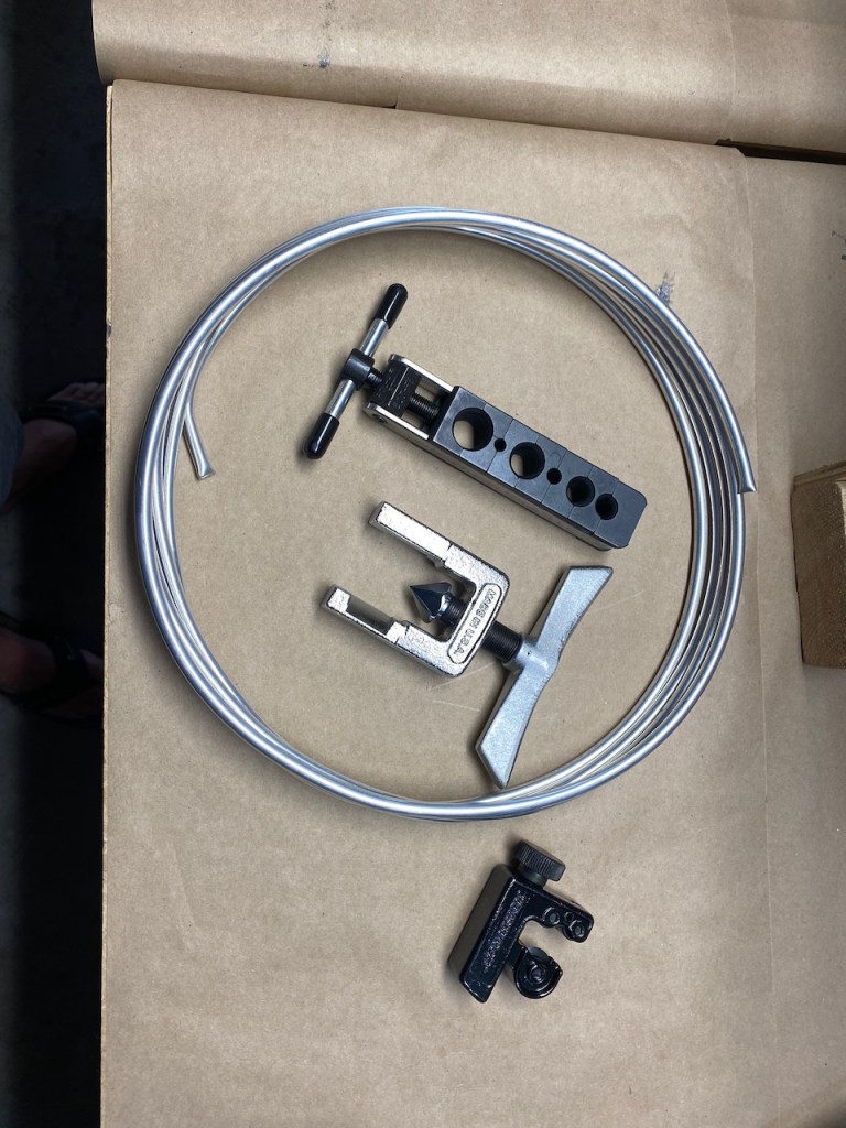
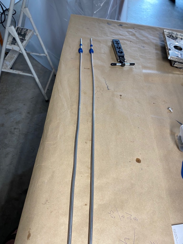
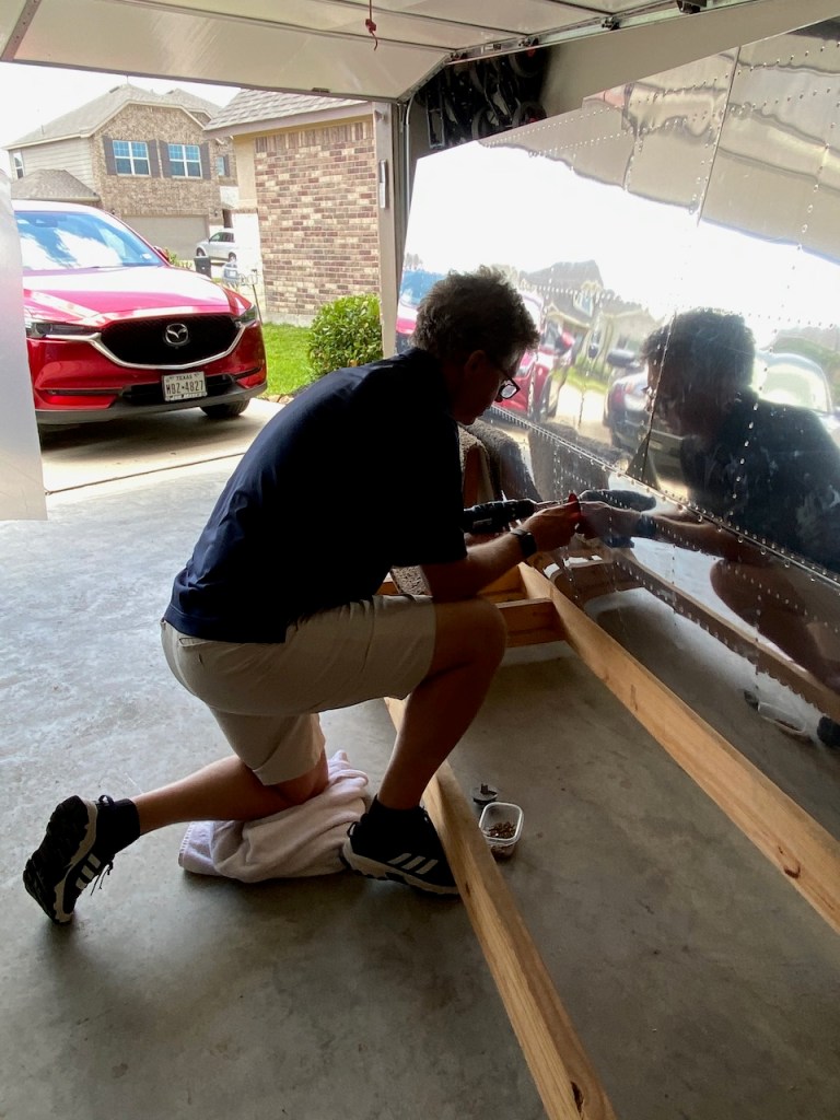
After the proseal, it was time for my first attempt at plumbing. What follows is the installation of the fuel vent line. It uses aluminum tubing and a special tool to flare the ends for the fittings.
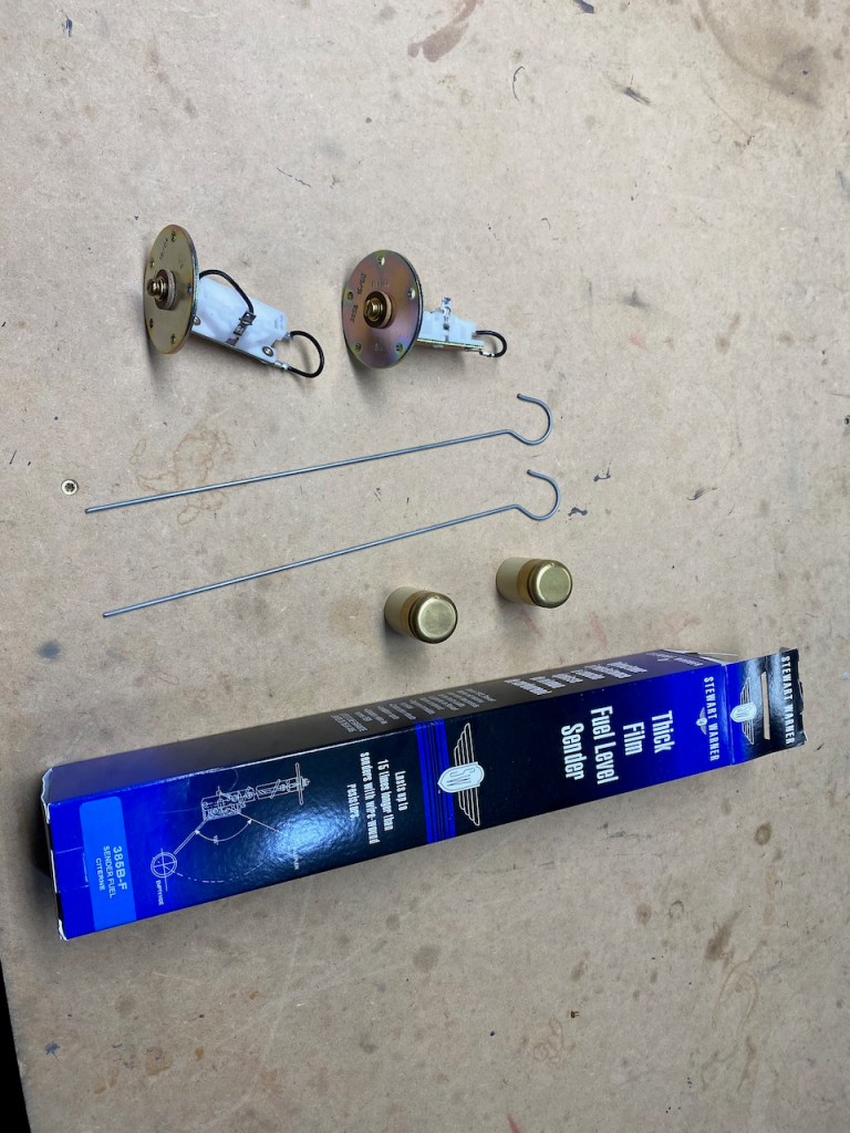
Then it was time to install a Fuel Level Sender into each tank. This basically uses a float to detect the level of the fuel. As the float moves up or down, the electrical resistance of the sender changes which is transmitted to the fuel gauge which obviously tells me how much fuel remains in the tank.

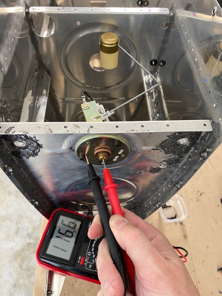
Measuring the resistance between the ground and the plate attached to the Fuel Level Sender tells me things are working.
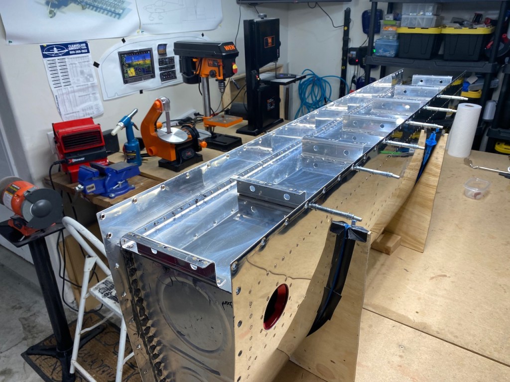
The final step for each tank was to attached the baffle to the top of the tank (which is actually the rear of the tank when mounted on the wing). Instructions say to put big globs of Proseal in the corners which is a common place for leakage. Perhaps I should have read that closer.
The baffle is then riveted. At this point, I am about 10,000 rivets into the build of about 22,000 rivets.
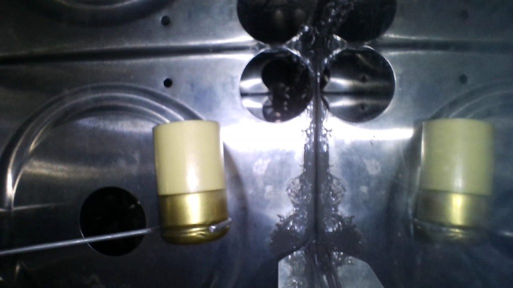
I bought a endoscope or borescope off Amazon which allows me to peer inside small spaces. It uses a smartphone as a screen, and it turned out to be money well spent. Below is a peek inside the tank at the fuel level sender float.
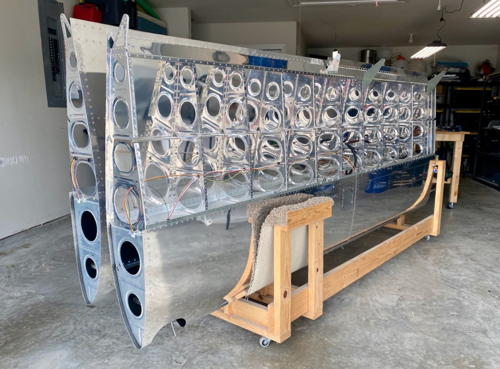
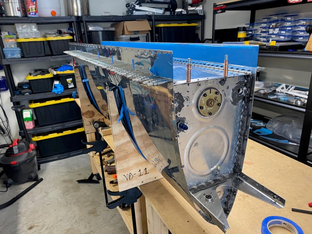
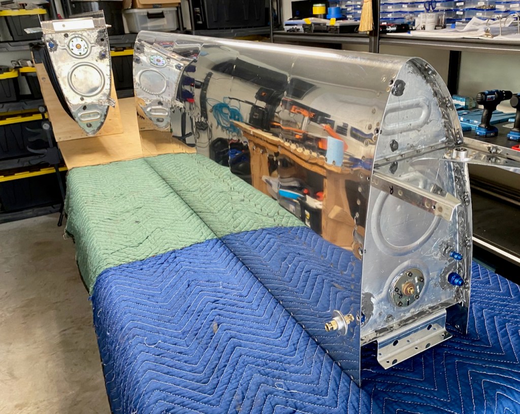
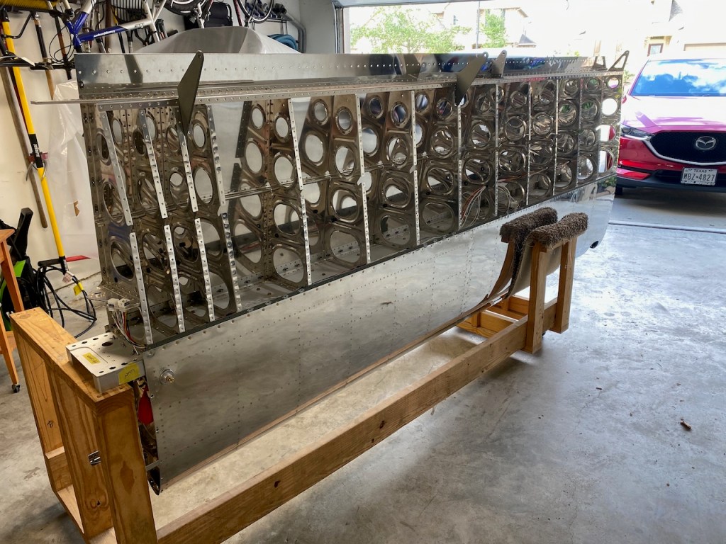
This is showing the two tanks ready for leak testing.
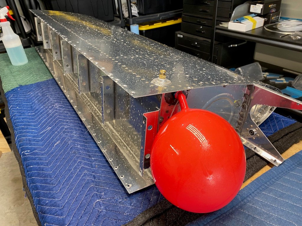
Leak testing, as suggested by Vans Aircraft, is to attach a balloon to a fitting, and then pressurize the tank with air. The balloon’s purpose is to prevent you from putting too much pressure inside the tank. They say not to put more than 1psi into the tank, and a balloon can only hold about 0.15psi. So, bursting the balloon with air would ensure you stay way below the max pressure rating of the tank.
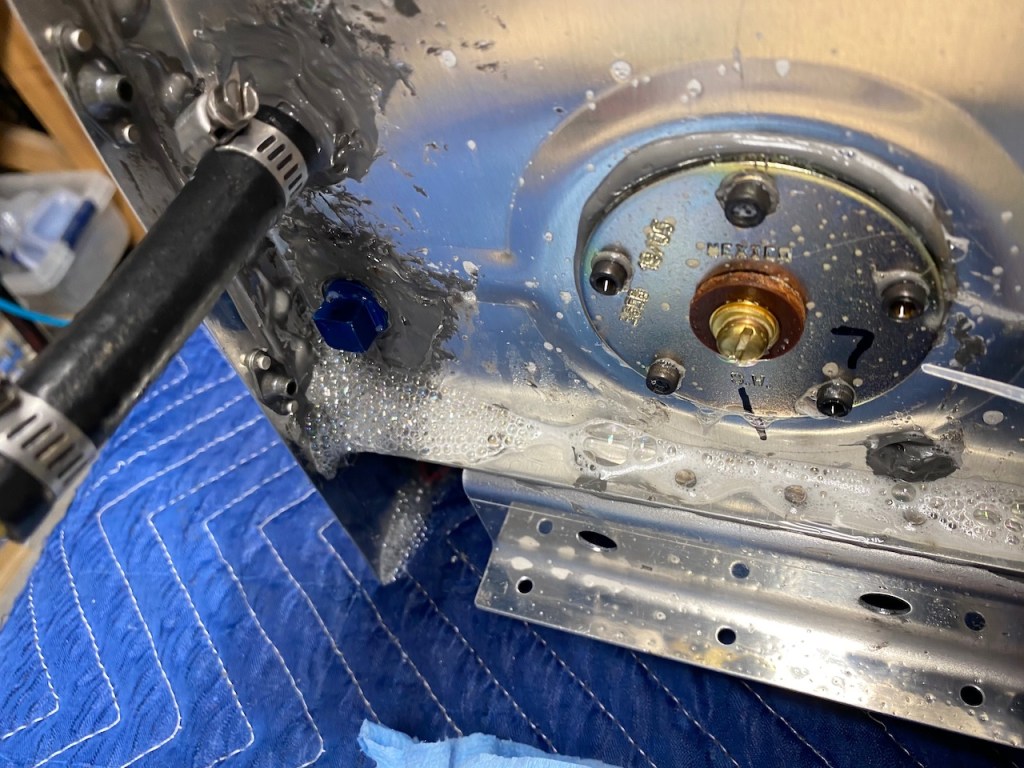
After the balloon is filled, the procedure is to spray down the outside with a water and dish soap mixture to see of there are any leaks. Leaks would be seen by a bunch of bubbles.
The left tank checked good with no leaks. You can see here the tank is covered with soapy water.
The tank was then immediately installed on the wing. 59 brass screws plus some bolts into the brackets on the rear of the tank holds it in place.
The right tank wasn’t as good. I immediately found a leak in the corner of the baffle – right where the instructions say it is a common source of a leak. I guess I didn’t put enough blobs of proseal there.
The bubble formation was very noticeable.
Looking closer, there was an obvious hole in the proseal.
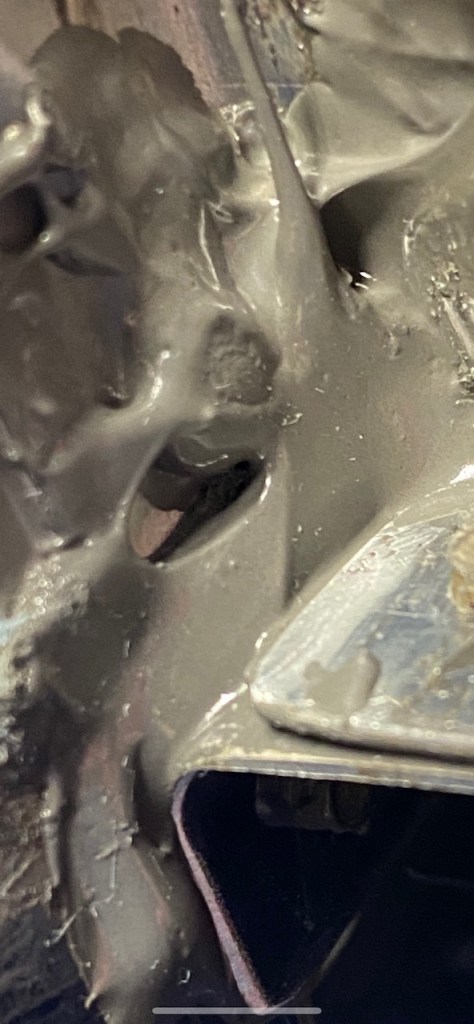
I decided the best course of action was to get inside and add more proseal to the inside corner. I ended up removing the fuel level sender, and used an acid brush dipped in globs of proseal to mash a bunch of material into that corner. The endoscope was very helpful in locating where I was trying to place proseal.
This shows how I held the acid brush which went into the hole where the fuel level sender is installed.
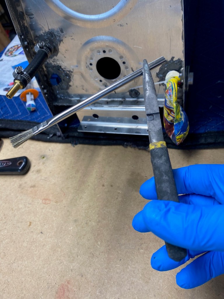
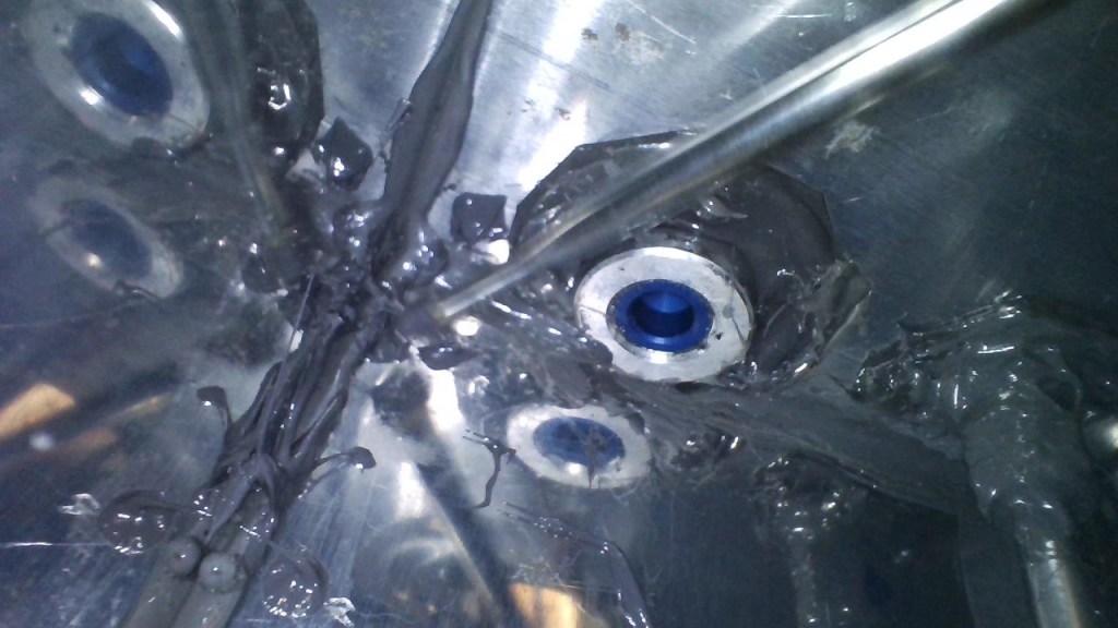
You can see here the acid brush (long straight aluminum piece from upper right to left of center) as I maneuvered it to the corner.
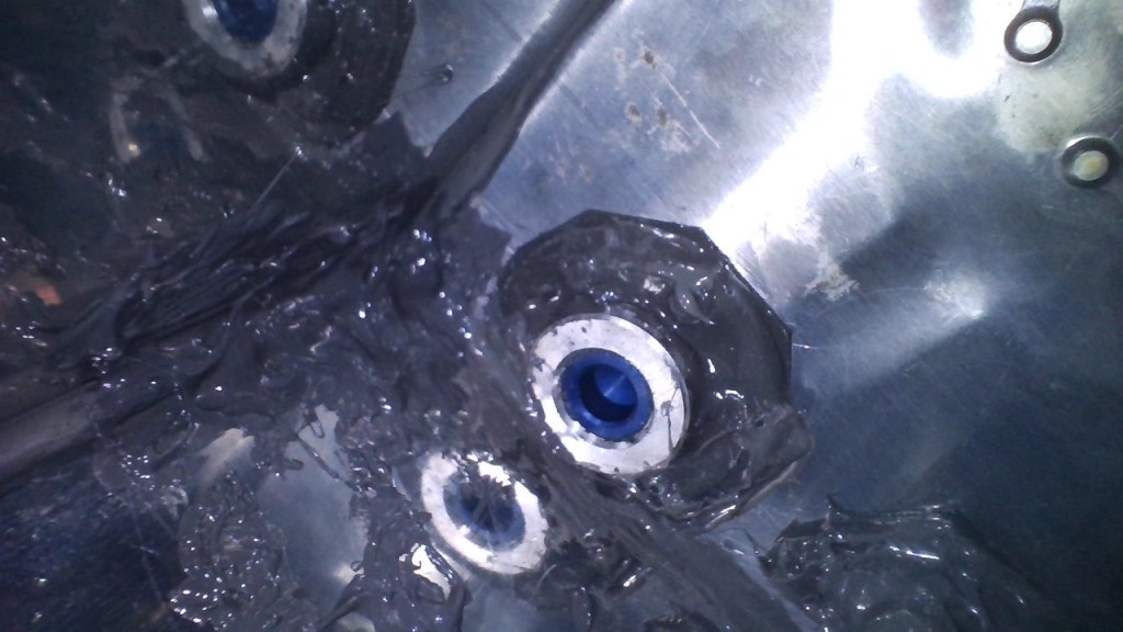
The end result was a bunch of gooey globby mess in the corner. I also added some to the outside. The result was no more leaks.
This shows both wings with the tanks installed. I have read that everything is downhill from here. We will see. Nevertheless, it is a big relief to have this behind me.