
When building an airplane, everybody knows about and comments on the riveting. Well, riveting gets all the glory but match drilling, deburring, and dimpling is the grunt work that nobody thinks about. These 3 tasks will definitely take up the majority of the build time.
With 3 days of a long weekend over Memorial Day ahead of me, my goal was to get the rudder complete before Monday night.
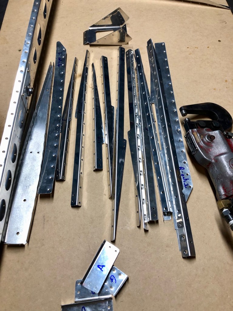
All the stiffners, ribs and the spar were put through the big 3 drudgery of matching drilling, deburring, and dimpling. This is definitely mindless work except for deciding which way the dimple should go. With a little thought before action, I didn’t seem to have a problem with this. Once again, the pneumatic squeezer made life simpler.
Next the left and right skins of the rudder were deburred. Care needed to be taken (with bold print in the plans) that you don’t take out too much metal when deburring the holes.
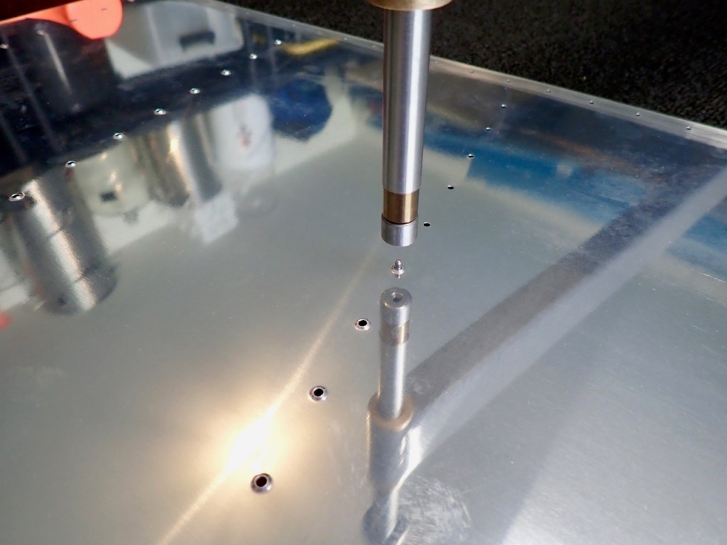
After the dreaded double dimple with the previous go around with the skins, I made sure to set up the dimpling table correctly with the C-Frame dimpler. Many hammer blows later, I thought the results were pretty good with no evidence of denting around the holes.
Then it was time to back rivet the stiffeners to each skin. It was very important here to keep the back rivet plate lined up with the stiffeners. If I did not, sure disaster would have struck me, and the rudder may have taken its own flight out of the garage in disgust. Well, it didn’t happen, and I successfully riveted each stiffener with good results. I was rather surprised how easy this was.
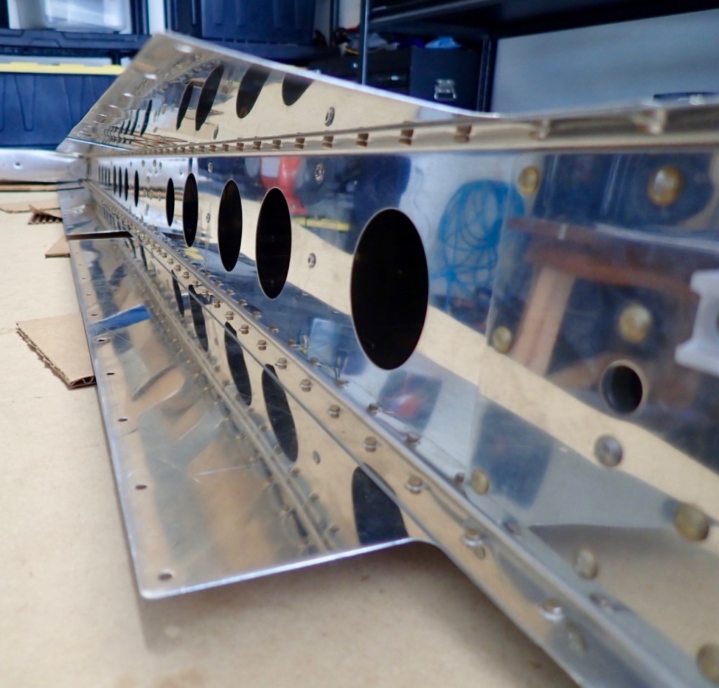
After the addition of the stiffeners, the shear clips were added. These are attached with a Blind Rivet or otherwise known as a pop rivet. These were the first of many Blind Rivets in this section. I was looking forward to using Blind Rivets but later decided a rivet gun is a much better and easier piece of gear.
Now, for the fun part which caused sleepless nights thinking about this: the rudder trailing edge.
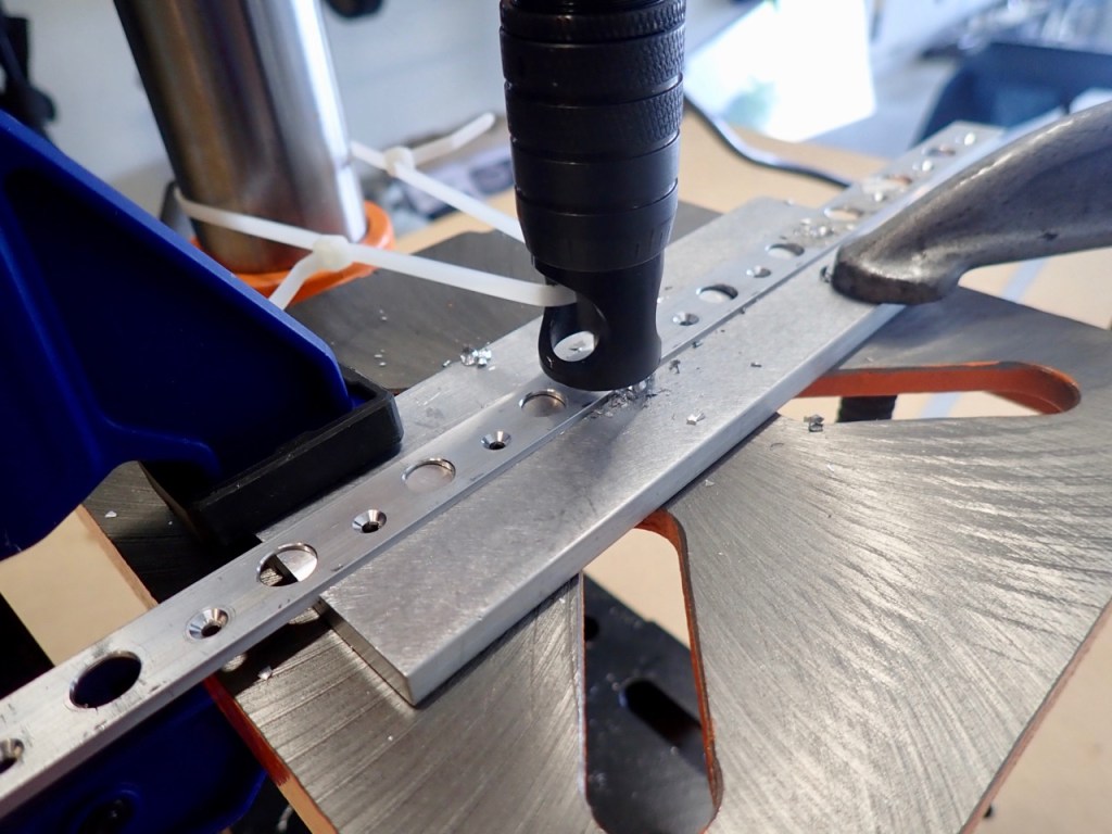
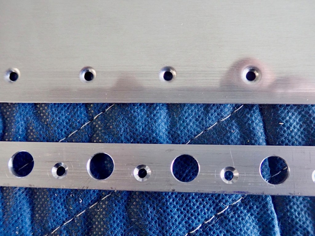
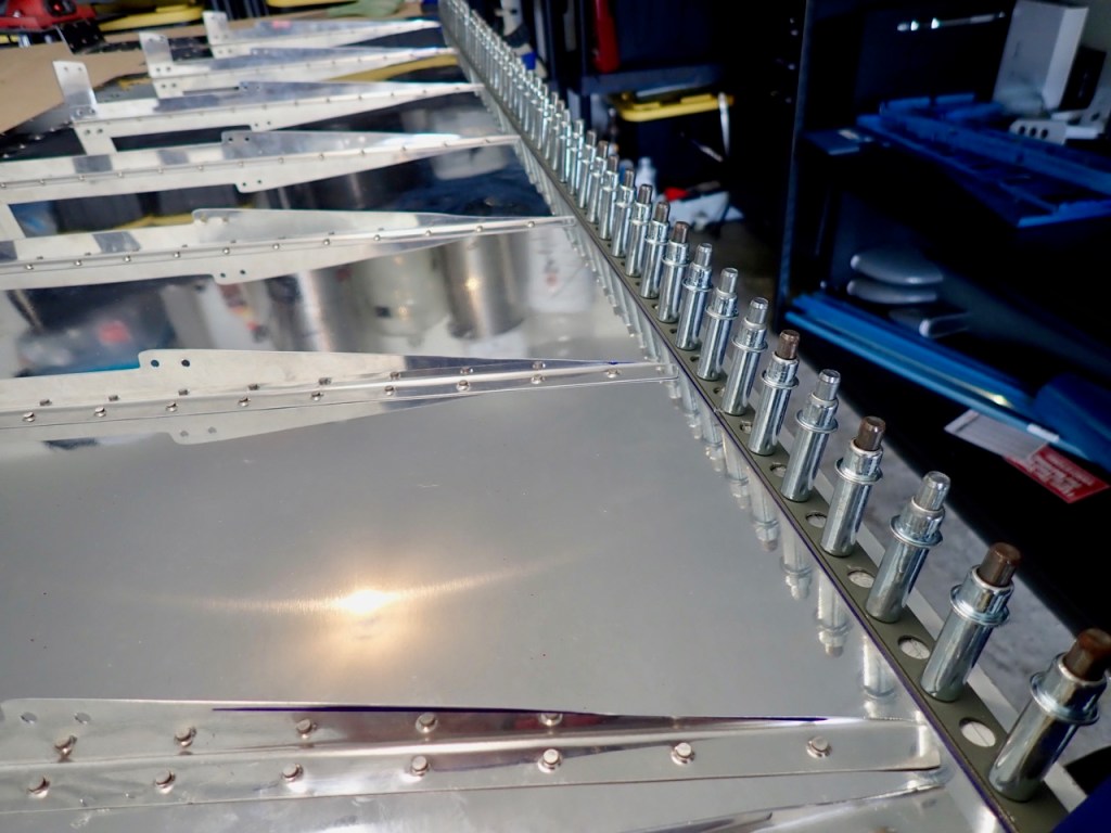
The first step is to perform some drilling steps in the holes followed by countersinking each hole on both sides. A microstop countersink along with a Cleveland Aircraft Tools trailing edge wedge tool allowed me to countersink each hole perpendicular to the trailing edge surface. The trailing edge is shaped like a wedge, and without this wedge tool, I would have had to eyeball the perpendicular angle which probably would have had predictable results (no bueno).
The countersinked holes allow the dimpled holes in the skin to fit flush into the trailing edge wedge. The end result of all of this was to get a very straight trailing edge. Without a straight trailing edge, the airplane would have undesirable flight characteristics which is very undesirable.
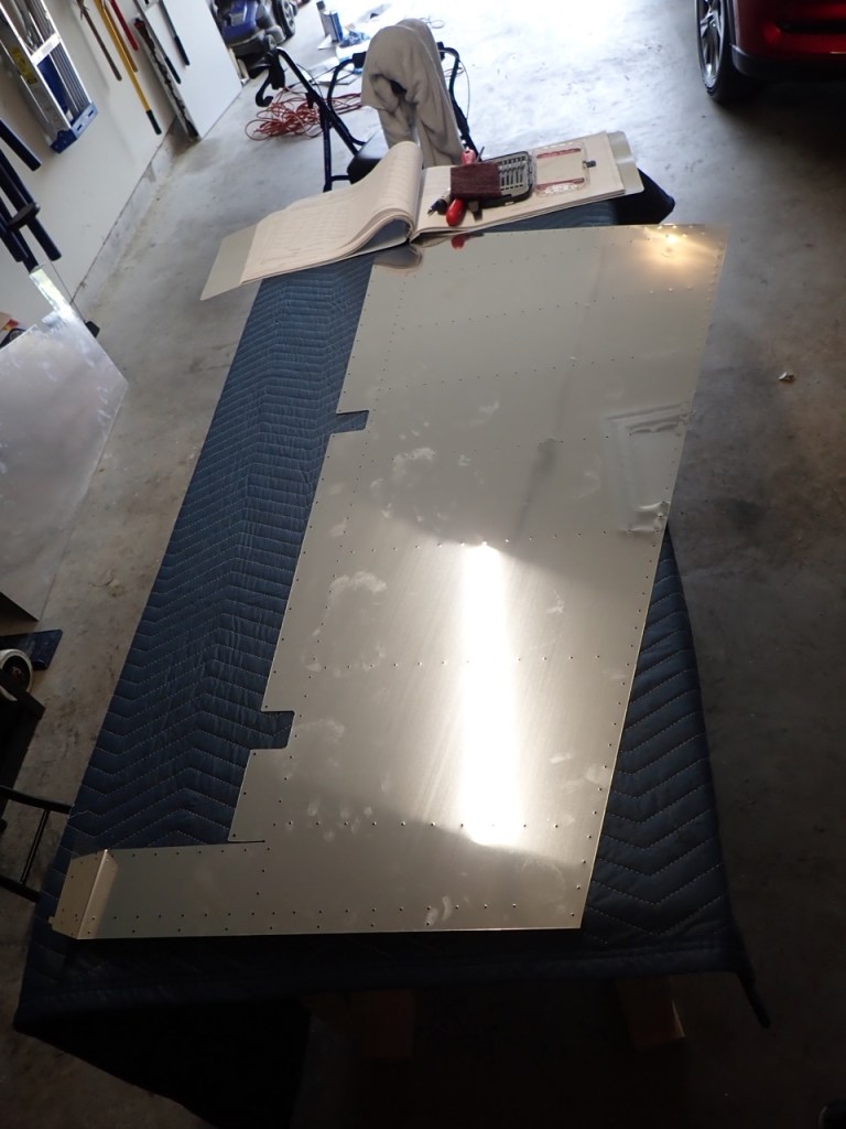
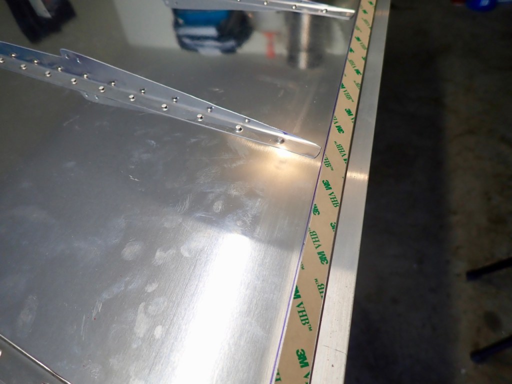
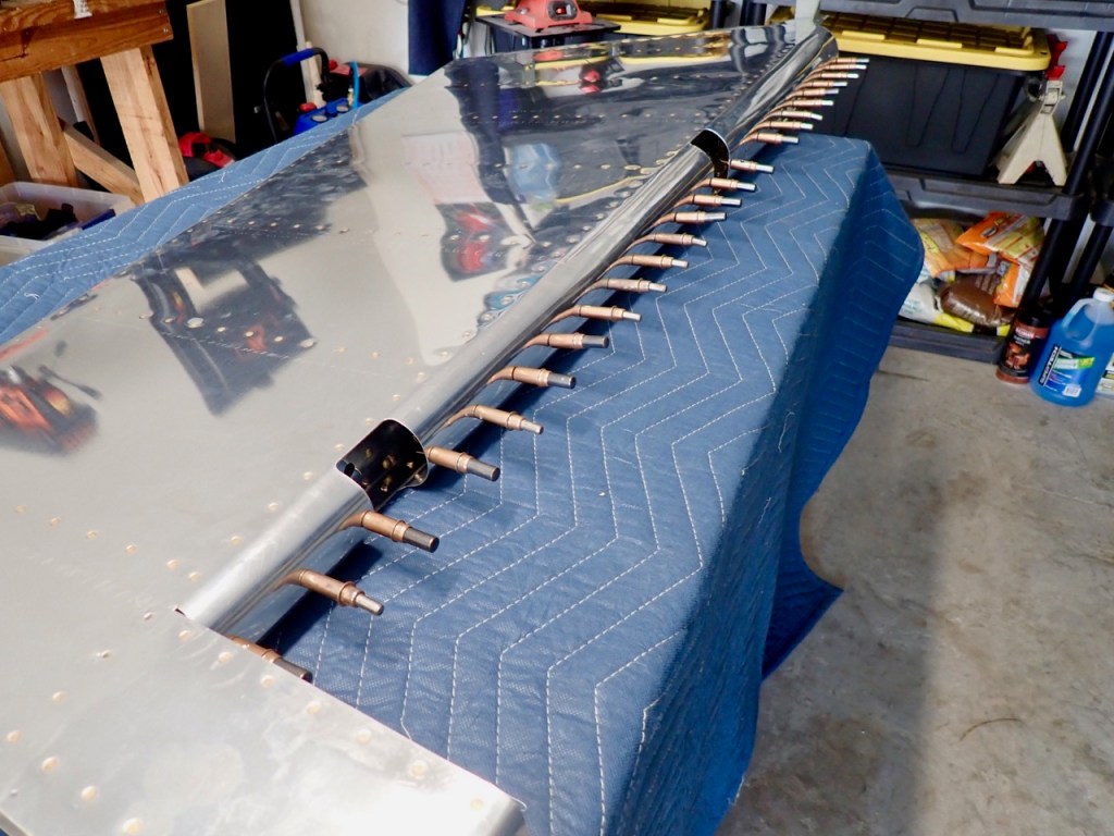
The trailing edge wedge was then cleco’d to the skin. You can see the wedge is primered which is one of the rare pieces I thought I should apply primer to: however, I later realized this was a mistake so I removed the wedge and sanded off the primer. The reason for this is the primer is not a good surface for the 3M tape to adhere to which is the material seen in the following photo.
The purpose of the tape is to keep the ends of the two skins bonded together tightly while the rivets are applied. This helps to ensure straightness which is very desireable.
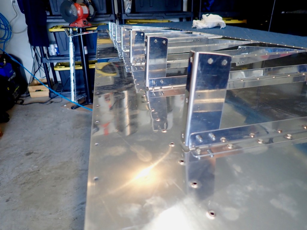
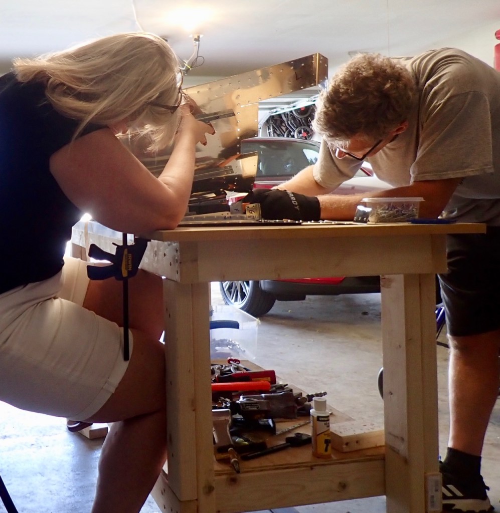
After the trailing edge wedge was attached, it was time to put the two skins together. The technique here is to Blind Rivet each stiffener together from one end to the other. An assistant like my trusty co-pilot is needed to basically reverse peel the skins together as each set of stiffeners is riveted together.
More pop-riveting followed which basically attached the underlying framework to the spar. By now my hands were raw and pectoral muscles were sore from all the squeezing.

The results were good but the trailing edge riveting loomed ahead.

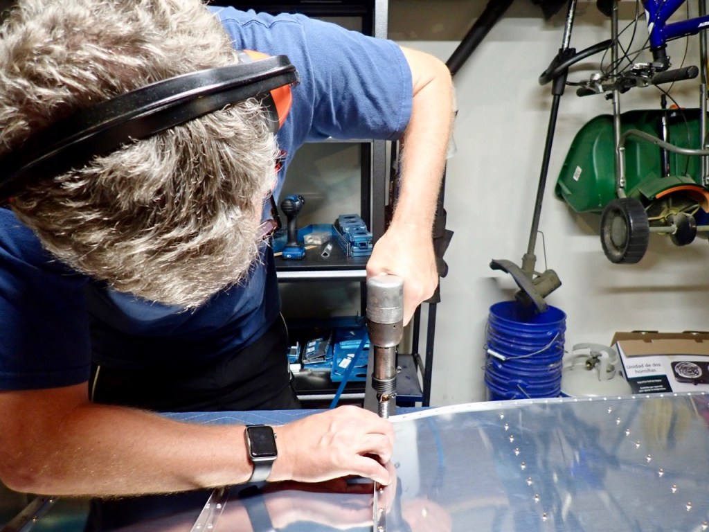
It really was not that bad. The technique I used was to back rivet halfway the shop head of each rivet (with a back rivet plate underneath) then flip the rudder over and then use a flush rivet set to fully seat each rivet against the back rivet plate. The key is to go in the recommended pattern from Vans and take your time. I did not goof on any rivet.

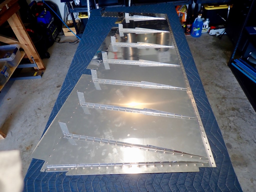
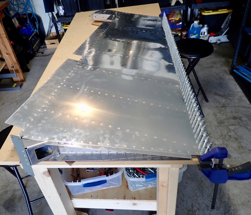
I think the edge came out very straight. See for yourself.
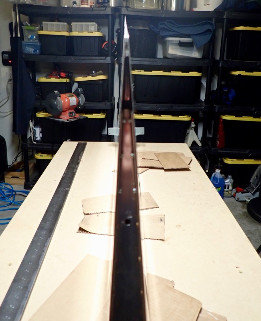
The last task was to round the leading edges from the straight pieces of metal seen in the above photo to a rounded piece of metal seen below. Easier said than done. This was physically demanding with the use of a broomstick and duct tape. Due to orders from my trusty co-pilot, I had to step away (due to frustrations), play golf, and return later that evening to finish the bending.
The leading edges were finished off with some more pop-rivets.

The result was a completed rudder and a part that looks like it attaches to another previously finished part.


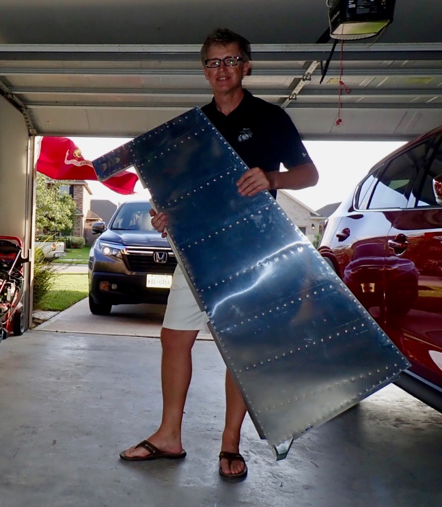
It was Monday night, and my goal was met (with some unashamed promoting of the USMC on this Memorial Day).
On to the horizontal stabilizer…
