
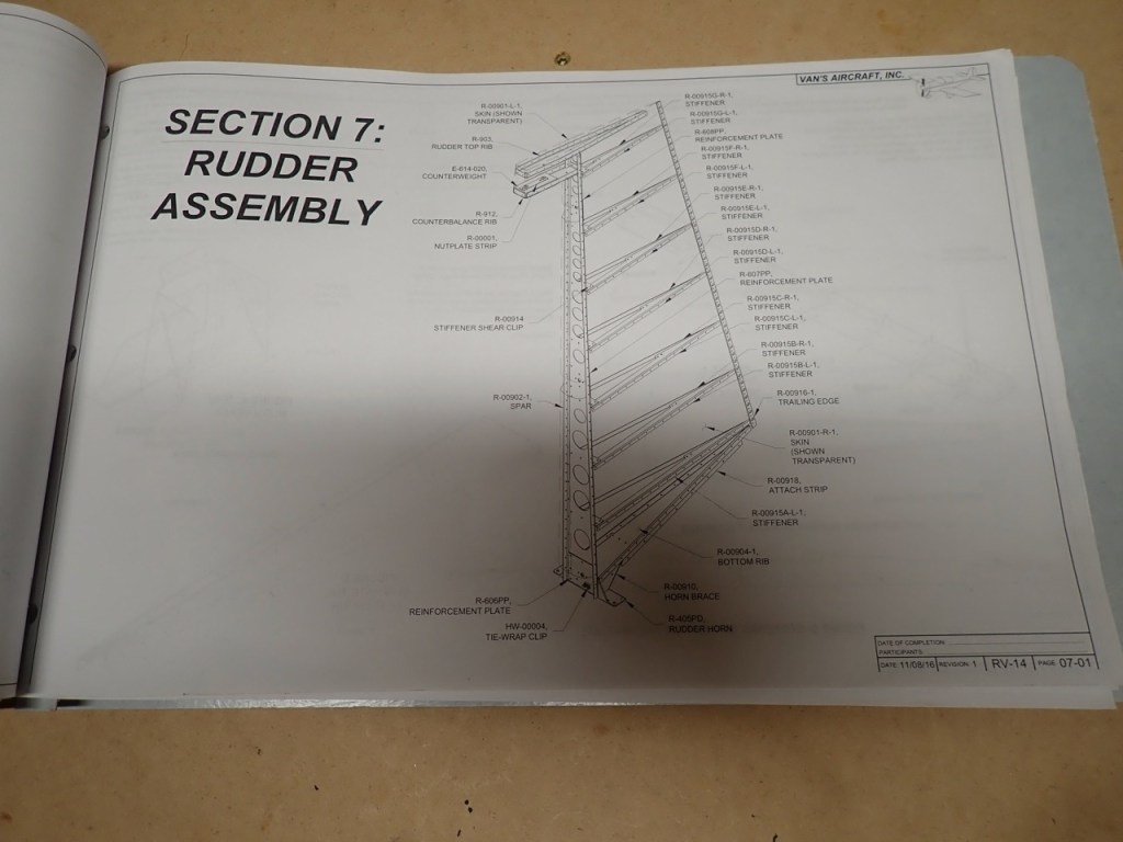
From looking at the plans for the rudder, the level of complexity appears to be increasing exponentially. This is mainly due to the assembly of the trailing edge of the rudder. This section of the rudder will require a “double flush rivet” technique of which I don’t think I fully understand at this point. Luckily the internet is full of excellent resources. Some of my fellow RV-14A builders have made incredible step by step records of their builds. I am not sure I will even come close to the recorded level of detail that these other guys are doing.
The one part that is causing anxiety is the straightness of the trailing edge of the rudder. It has to be absolutely straight in order to maintain good flight characteristics of the airplane. Hopefully a future post to this blog will show an image of a straight trailing edge.
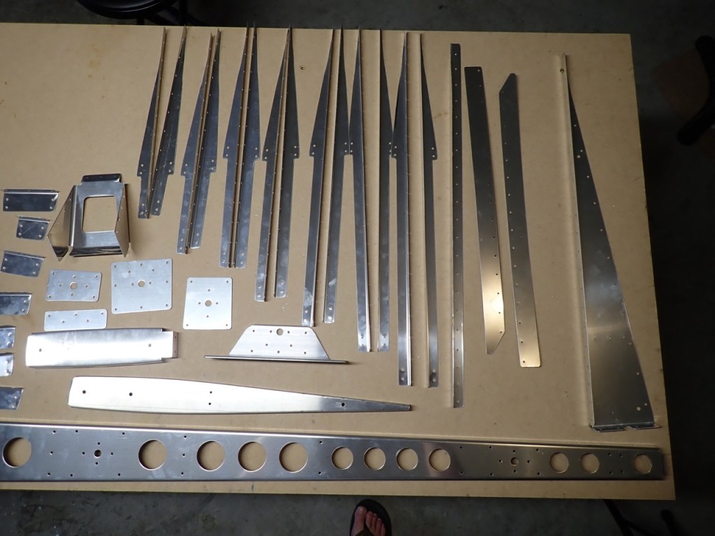
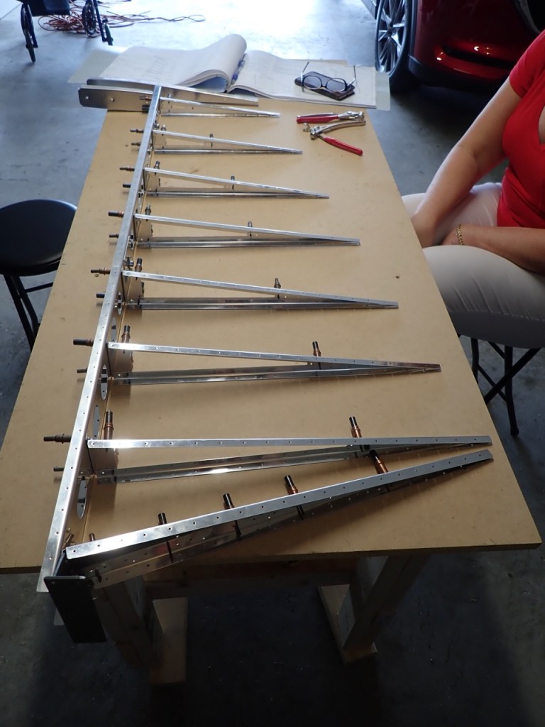
Like the Vertical Stabilizer, the Rudder assembly started out by gathering the various frame parts, removing the protective blue film, and deburring the edges of the parts. Deburring is basically removing all sharp edges of all the aluminum parts. Sharp, angular edges are a source of stress cracks that may show up later in the life of the airplane. Rounded edges reduce the possibility of stress cracks. This applies to all parts used inside the skins, all holes in all the parts, and the edges of the skins. A variety of methods can be used including dedicated deburring tools, scotchpads, a scrotch-brite wheel on a grinder, files…even a large drill bit can be used to deburr holes. I am still experimenting with all of the above to determine which is best.
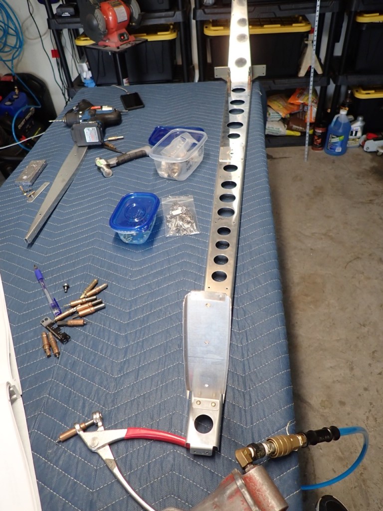
Here are the various parts used in the frame of the rudder. The arrow looking pieces were trimmed to the shape seen on the bandsaw.
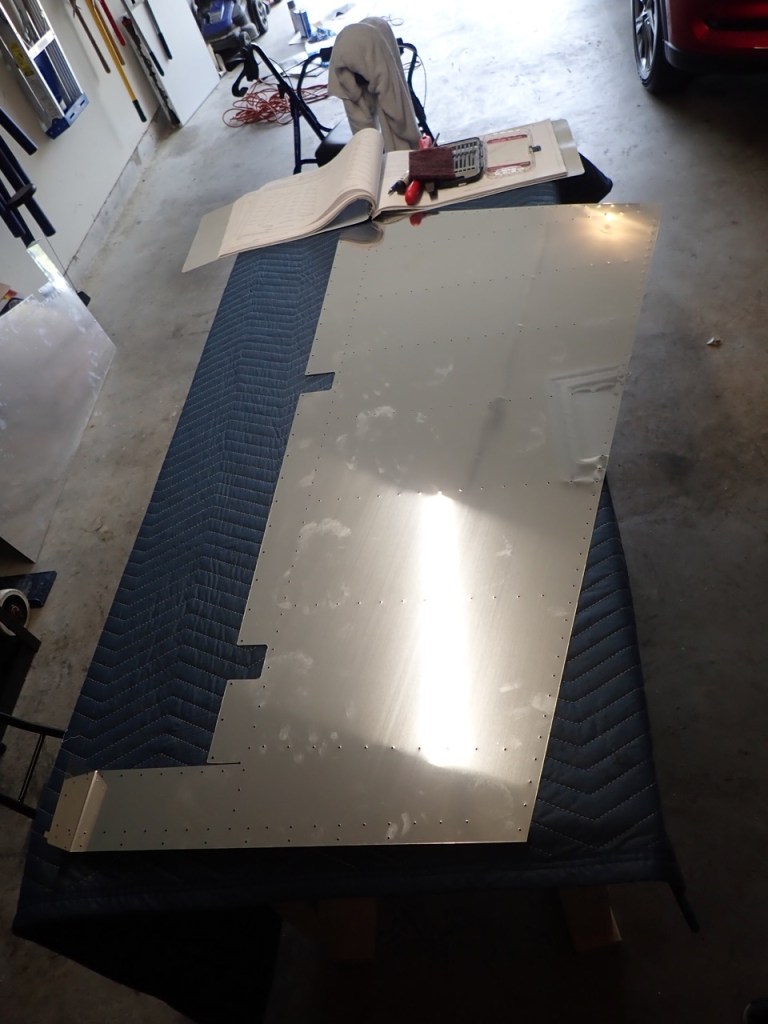
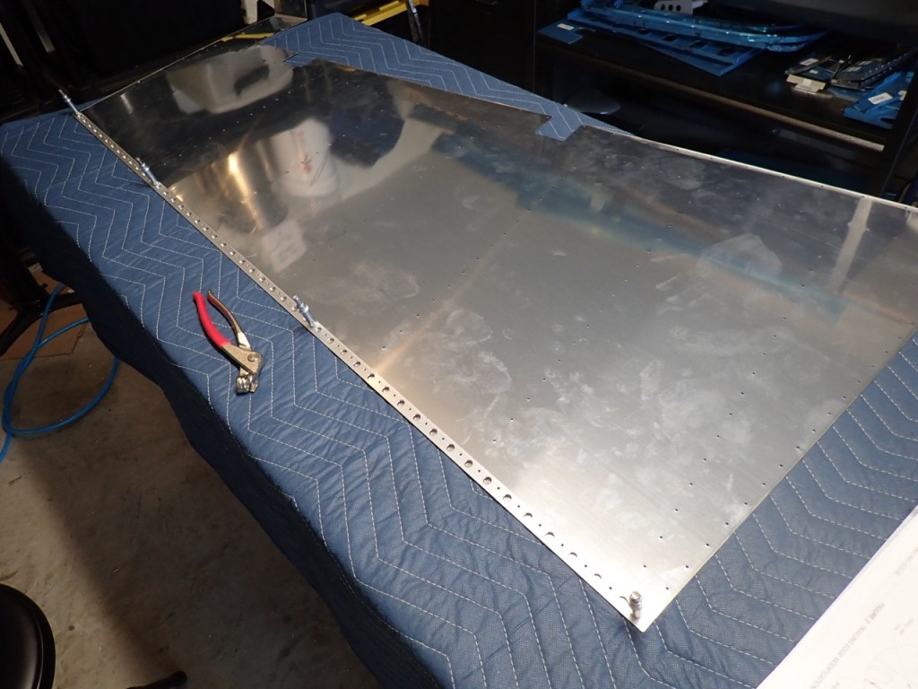
Unlike the Vertical Stabilizer, the rudder skin is two separate pieces surrounding the frame. The leading edges will be rolled into each other and the trailing edge will be riveted as previously described.
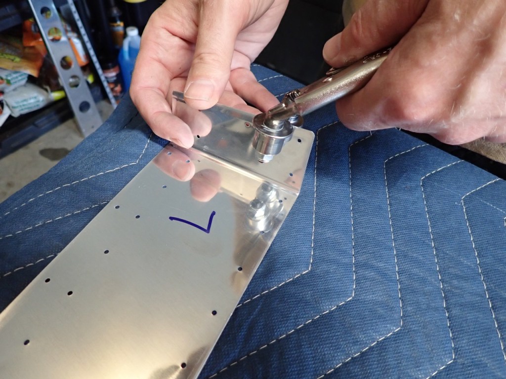
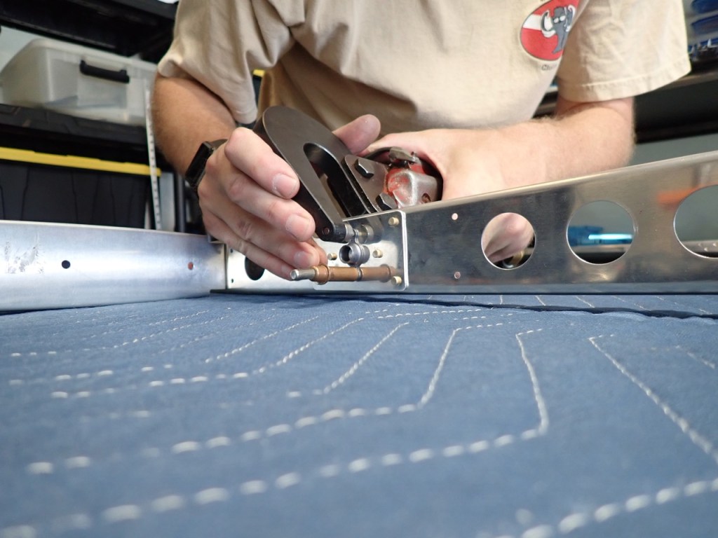
Another special tool purchased was an Edge Roller tool. This bends an edge slightly so that when the skin is riveted next to another skin, the edge outside the row of rivets stays flush with the other skin. It is a really slick and easy tool to use.
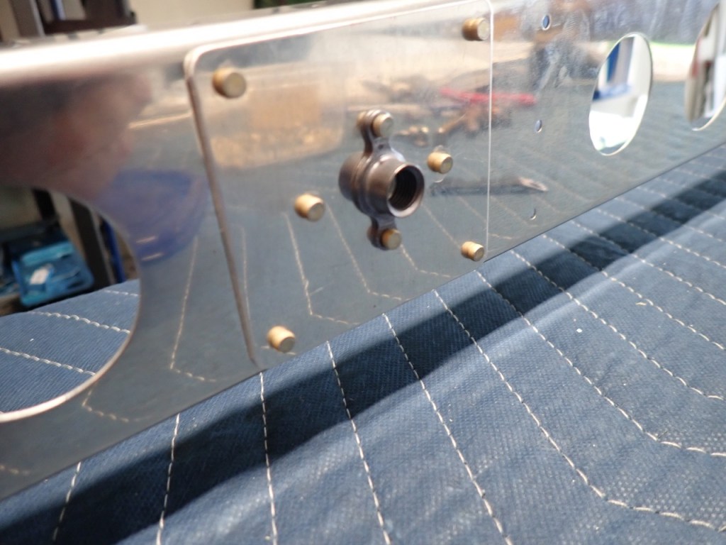
Like the VS, the various parts of the frame are riveted together with some doubler plates, ribs, and even my first set of nut plates.


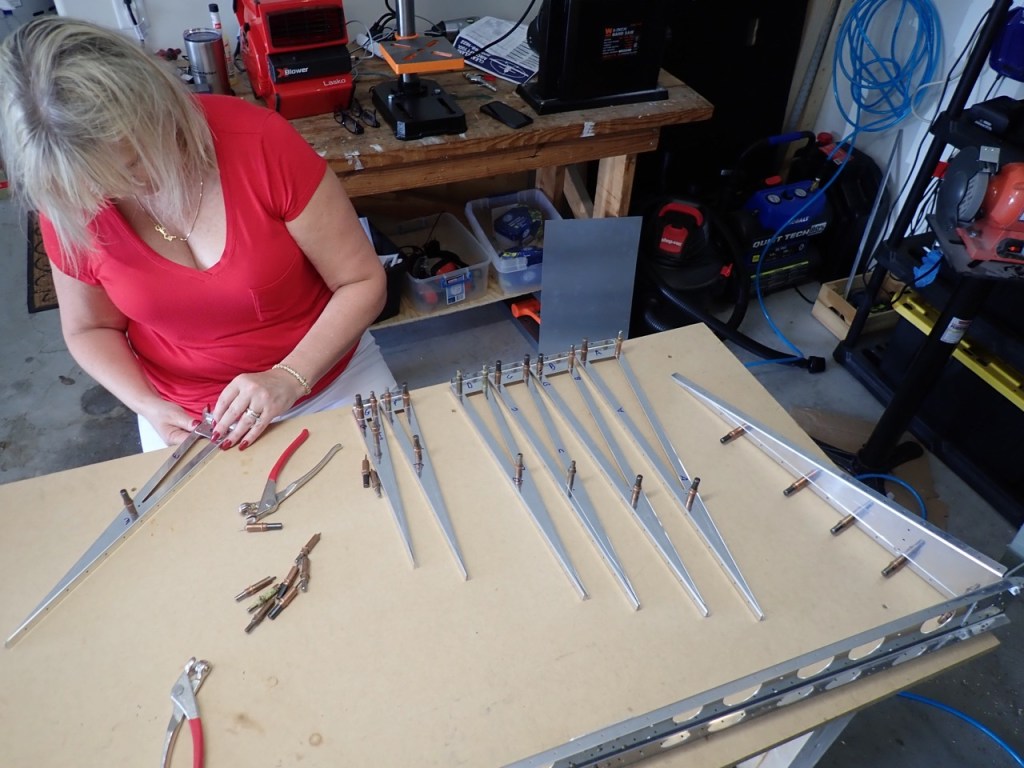
The arrow looking things seen in the previous photos are the stiffners used to strengthen the rudder skins. They will be back riveted to the skins in the next sections.
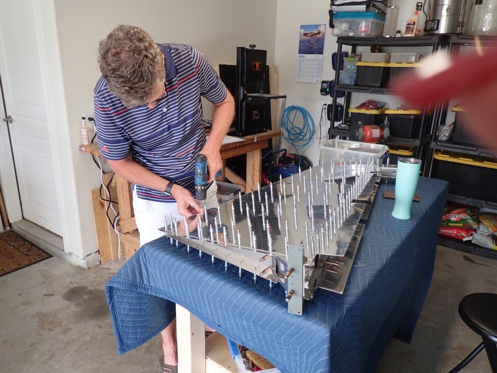
First, they are cleco’d together and further cleco’d to the spar seen above. My trusty co-pilot is starting to get the hang of using cleco pliers.
Before cleco’ing the skin to the frame, the first step in the dreaded trailing edge is to cut the trailing edge to length and mark its location on each rudder skin.
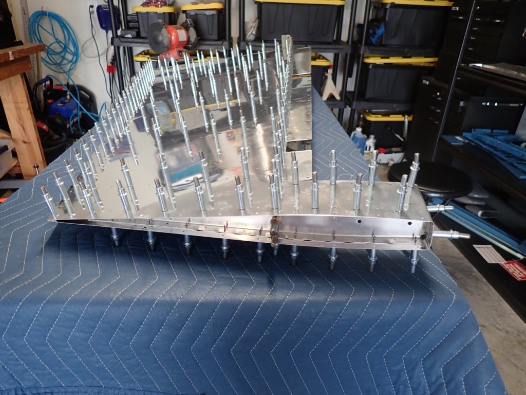
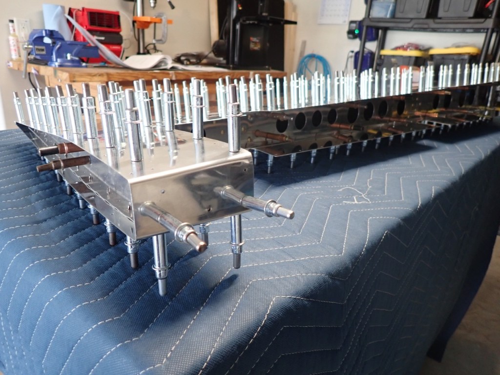
Each skin was then cleco’d to the underlying frame. The goal here was to get everything attached and the respective holes lined up for final drilling. Final drilling is drilling through each hole and the hole where it is lined up with in order to widen it a bit for the rivet that will be placed in the hole during a later step. Except for the trailing edge, I only put a cleco in about half of the holes. The idea is to final drill the holes without a hole and then shift the clecos to the open holes, and then drill the holes now vacated by the clecos.
Yes, this is a lot of holes and a lot of cleco’ing.
The instructions say to put a cleco in each hole of the trailing edge while final drilling these holes. Presumably this is to maintain the straight trailing edge. So far so good.
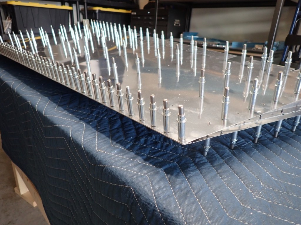
The next steps are to remove the skins, deburr all the holes, and then dimple. Hopefully the dreaded double dimple does not rear its ugly head.
